


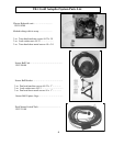
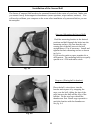
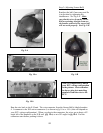
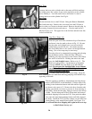
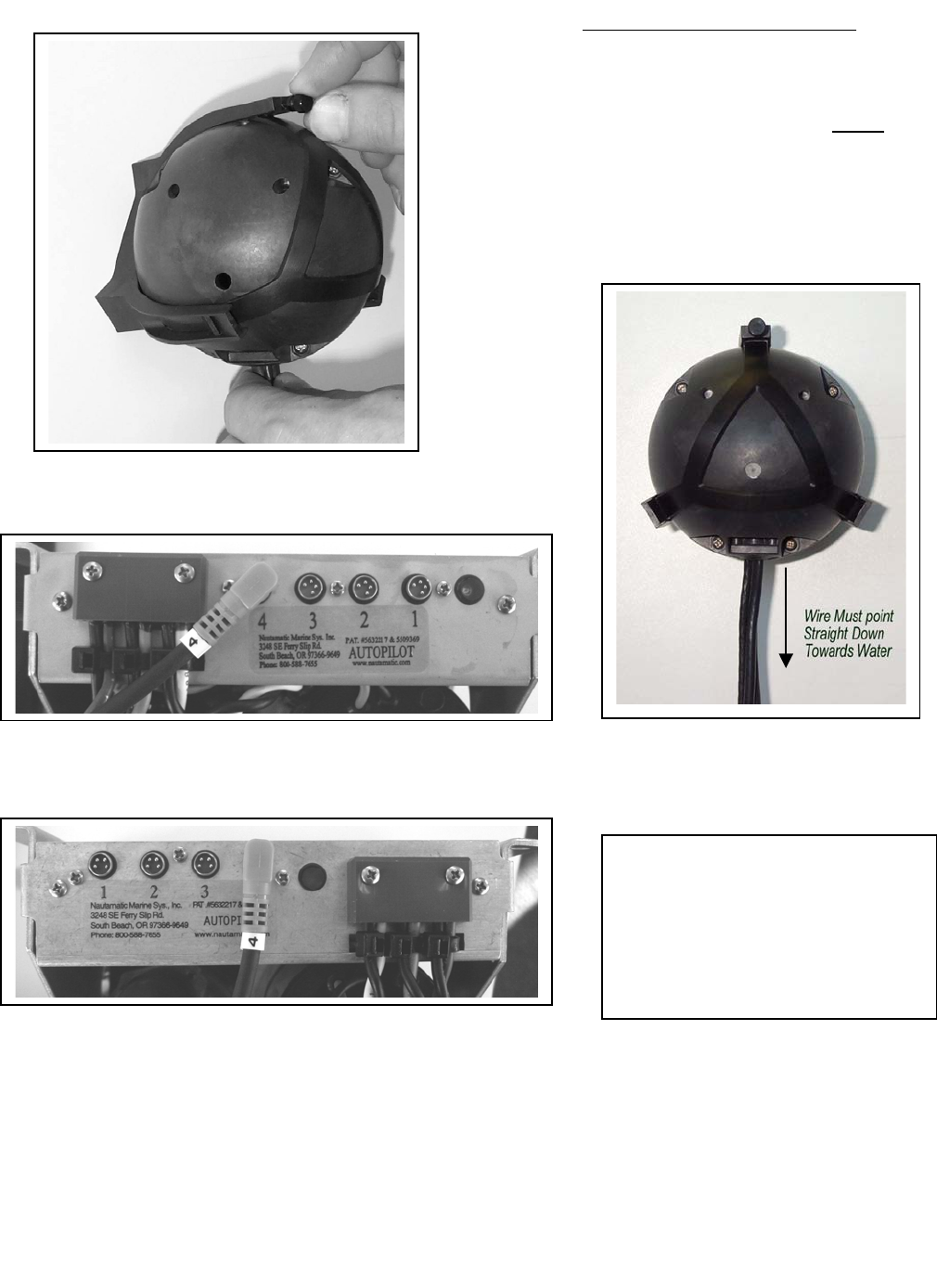
Step 3 (Adjusting Sensor Ball)
Readjust the ball if necessary and fix
it in position by tightening the
thumbscrew. See Fig 9-A. Make
sure that the wires from the Sensor
Ball are pointing straight down out
the bottom; otherwise the sensor ball
will not work properly. See Fig. 9-B
Fig. 9-A
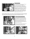
Fig. 9-B Fig. 10-a
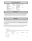
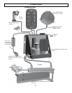
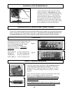
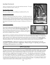
Note: It is important to match
your ECU wiring configuration
to the picture. Just remember
to always plug into matching
numbers from the wire to the
ECU.
Fig. 10-b
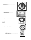
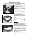
Run the wire back to the E-H unit. The wire connector from the Sensor Ball is labeled number
4. It connects to the E-H unit at connector 4, as shown in fig.10-a or 10-b. (this will depend on
your ECU wiring configuration). When you plug in the connectors, the wires go at about a 45q-
angle left of the numbers on the E-H unit (fig. 10-a) or at a 90° angle for fig 10-b. Feel the
connectors start before pushing it down.
12
12