


6
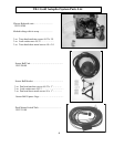
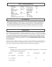
E-H unit 6.5”H x 7” W x 5” D 8 lb
Sensor Ball 3.6” Dia. Cable length 18’ 2 lb
Remote 5”x 2.5”x 1” Cable length 18’ 1 lb
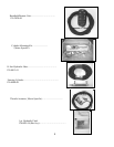
Deckmount/Tach 5/8”x 2” Cable length 6’
Battery Cable Cable length 9’
Fluid 1 pt. BioSOY Oil 1 lb
Supply Voltage 11.5 – 14.0 VDC
Maximum Current 12 Amperes
Inline Fuse ATO 20 Amp
O
p
eratin
g
Ambient Tem
p
erature 20 – 120 de
g
F
TR-1 Gold Specifications
Introduction
This manual comprises two major sections. The first section is a guide to installation of
the “onboard” components of the autopilot system on your boat. The second section is a
guide to adjusting and operating your system. Installation instructions for the throttle
actuator and steering cylinder are motor specific and are provided in separate manuals.
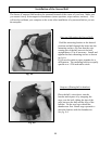
Preparation
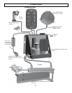
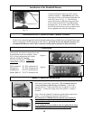
You will be hard mounting three autopilot components in your boat: 1) The Electrohydraulic
Unit. 2) The Deckmount switch. 3) The Sensor ball. These components are shown in relation
to each other and to the engine mounted components in the System Layout diagram on page 8.
As indicated by this diagram, the Electrohydraulic unit and the Deckmount switch are to be
located near the kicker and the Sensor ball is to be located FORWARD OF THE CENTER
OF YOUR BOAT
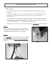
Spend some time to figure out where you are going to mount all of the components before you
mount any of them. Place the components where you expect to mount them and verify you
have access to and routes for the cables and hoses that connect the components.
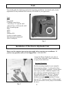
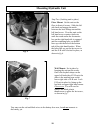
x Mounting Screws
Mounting screws are provided for through and blind hole applications. You may choose
to drill and tap the mounting surface.
SCREW TAP DRILL TAP CLEARANCE PILOT
#8 – 32 machine #29 .136 dia #8 –32
#8 – 32 machine 3/16
#8 s
h
eet
m
eta
l 1
/8
6