


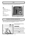
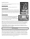
Installation of the Deckmount and Tach
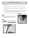
If the material you wish to mount the Deckmount
switch in is less than ¼” thick: Drill a hole 15/32
Diameter perpendicular to the surface. Unscrew
the bezel from the switch and leave one washer on
the neck. Put the switch button, with washer,
through the hole from below. Screw the bezel on
to the top and your done. Refer to Fig.11
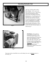
If the surface you want to mount the Deckmount on
is thicker than ¼ inch, Drill a 19/32 hole through
the surface. Unscrew the bezel from the top of the
switch and remove the washers. Slide the switch
all the way through the hole from the backside of
the panel. Apply some silicone sealer/adhesive to
the barrel of the switch. Screw the bezel, with or
without a washer back onto the switch and slide the
switch back into the hole. It may be necessary to
tape or otherwise hold the switch in place until the
sealer/adhesive sets. Alternatively, you can make
a custom sheet metal bezel/mounting bracket for
the switch.
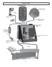
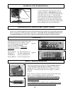
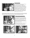
Step One: (Deckmount)
Fig. 11
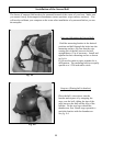
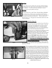
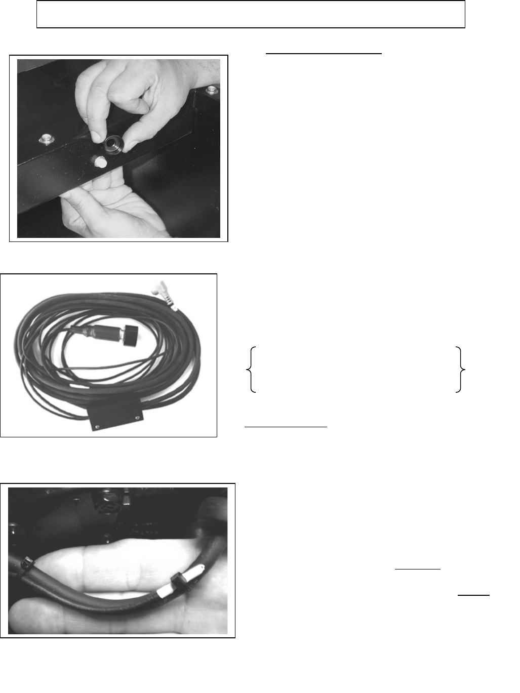
Step Two (Tach)
The Tach is the portion of the cable with a white antenna
end. The antenna end needs to be installed into your
outboard motor. The wire connector from the deck
mount/Tach switch is labeled number 1. It connects to the
E-H unit at connector number 1. Route the Tach portion of
the wire from the E-H unit back to the motor. Remove the
outboard cover. Route the cable through the grommets on
the front of your motor, then route the cable around the
motor to the spark plug wires. You will need to lay the
white or antenna end of the cable along side
of one of the
spark plug wires in your motor. Keep the antenna end at
least 1” from either end of spark plug wire. Do not
stick the end of the wire into the boot of the spark plug
wire. Use tie-wraps to attach the antenna end of cable to the
Spark plug wire. (Fig. 11-A)
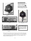
(After installation of your Autopilot, you will need to verify
your tach. Please refer to page 31, paragraph 2 for more
information).
Note: Route the cable for the tach on the
opposite side of the kicker motor that you route
the throttle actuator wire
.
Fig. 11-A
13