


Fig. 12
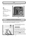
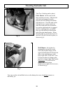
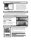
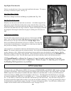
Installation of the Handheld/Remote
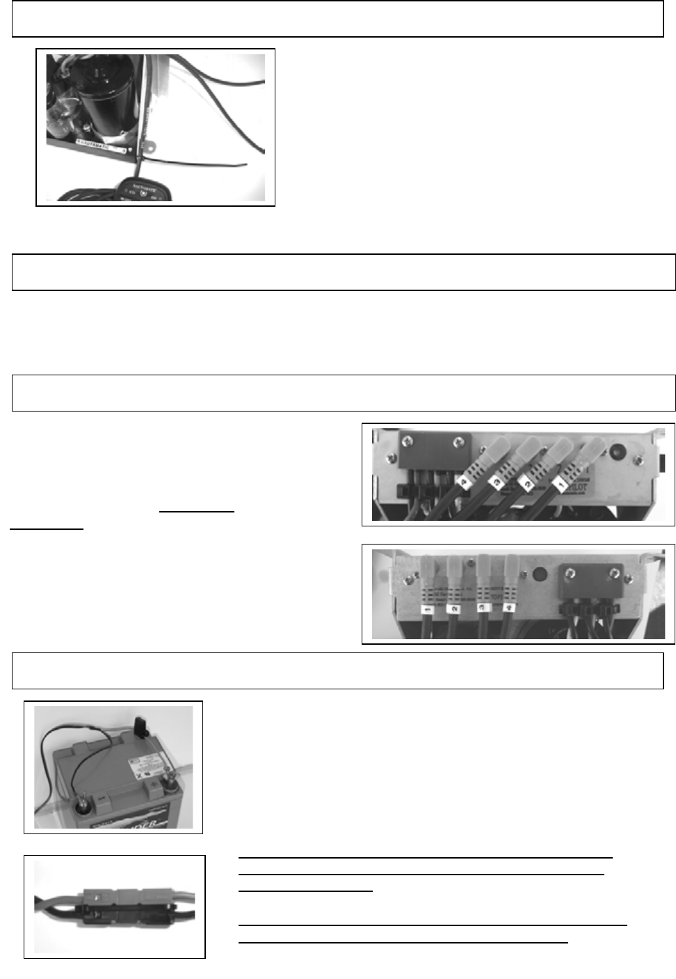
Connect the Remote cable to the ECU unit at
connector number 3. Strain Relieve the cable.
One place to do this is the bottom right hand side
of the ECU unit. See Fig. 12. This will help
protect the Remote cable from being pulled out
of the connector on the ECU unit and possibly
damaging unit. If you need to drill a hole in the
boat for the cable be sure to put a grommet in the
hole to protect cable from the sharp edges.
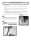
Installation of the Cylinder Kit and Throttle Actuator
Refer to the manuals supplied with the throttle and steering cylinder kits, and install these parts
before continuing with the procedures that follow. If you do not use the throttle actuator, it is
recommended that you coat #2 pico connector with a grease to protect it from corrosion.
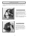
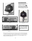
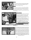
Battery Connection Installation
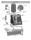
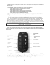
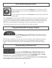
Connections
At this point, all electrical connections to the
Electrohydraulic unit are complete. Some
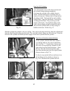
ECU wiring configurations are slightly
different see fig. 13-a and fig.
13-b for your variation. Verify these
connections
as follows:
Deck mount #1 To ECU connector #1
Throttle #2 To ECU connector #2
Handheld #3 To ECU connector #3
Sensor Ball #4 To ECU connector #4
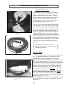
Now hook up the battery connections. We recommend that you
connect the battery cable directly to the battery. Connect the
ground side first. Connect the black wire to negative (-) side of
the battery. Connect the orange wire to the positive (+) battery
terminal.
Note: Do not be alarmed if connection sparks when connected to
battery, you are charging a capacitor inside the unit.
Do not cut out or eliminate the fuse portion on your battery
cable, it is there to protect your system and may void your
warranty if removed.
If you unplug the battery cable be sure to replace the tie wrap
around connectors to prevent them from separating.
Fi
g
.13-a
Fi
g
.13-b
14