


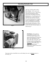
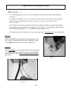
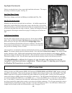
Step Eight (Check hose t)
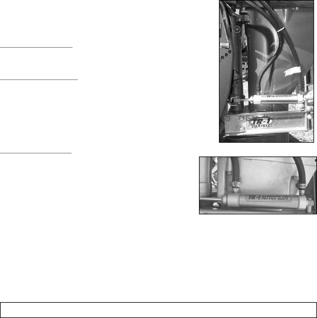
Check to see that the hose is free to move back and forth with motor. Tie wrap as
necessary to hold hose in place. See Fig. 18
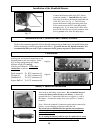
Step Nine (Hose Clamp)
Place hose clamps over hose and ttings at cylinder end. Fig. 18-a
Step Ten (Top off the system)
Manually turn the motor back and forth several times. Air bubbles trapped in the
tubing may cause the uid level in the tank to surge when the tiller is moved fast.
The more the tiller is cycled back and forth, the more air is purged from lines. Top
off the tank with uid when the surge is reduced. Replace the tank plug. Remount
the pump unit following the instructions on page 10, making sure all screws are
tight.
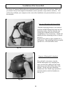
Verify Proper Installation
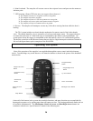
Press the deck mount switch to turn the system on. Put the unit in AUTO
mode. Press and hold the Straight Left Arrow button on the Remote. The
kicker will steer to the port. Press and hold the Straight Right Arrow
button on the Remote and the kicker will steer to starboard. Turn the motor
several times in each direction to verify that hose connections are tight and
that you have no binding of hoses or cables.
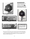
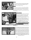
Get in position to see the kicker carburetor and the throttle actuator you installed, then press and hold the Up Arrow
button. The actuator should open the carburetor throttle. Press and hold the Down Arrow button. The actuator should
run the carburetor to idle. Pushing and releasing these buttons quickly moves the throttle by small amounts. Holding
them down changes the throttle by large amounts. Move the throttle to mid-travel and then press the IDLE/RES button.
The throttle should go to idle. Press the button again and the throttle should go back to the mid-travel position.
!!!! You will need to calibrate the Compass of your Autopilot, and will need to tune the
Autopilot to your boat and motor conguration. Please see page 33, adjusting your Autopilot
for Heading Hold operations on your Boat.
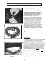
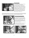
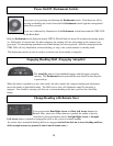
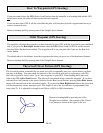
Check to see that your GPS transmits NMEA 0183 messages $GPRMB (RMB),and $GPRMC (RMC) before you hook
your GPS to the autopilot. These are the messages the autopilot must receive in order to steer with the GPS. Your GPS
NMEA output wires will usually be bundled with other conductors in the GPS cables. Look in your GPS manual for
instructions relating to NMEA output from the GPS to other devices. The GPS manual should identify two wires that
are named something like NMEA out (+) and NMEA out (-). Connect the NMEA out (+) to the red (+) and the NMEA
out (-) to the white (-) conductors in the stub cable with the blue tip at the Sensor ball. You will need to strip some of
the jacket from the blue tipped cable in order to get to the red and white conductors. 22 or 24 gage twisted pair wiring is
recommended for connecting this circuit. (See page 23 for more information on GPS.) You will need to calibrate your
compass and Set North in order for GPS functions to work. See pages 23 & 35
18
GPS Connections