


MI00/10056 rev. 8 — 05/2006-- page
11
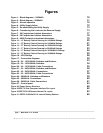
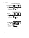
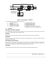
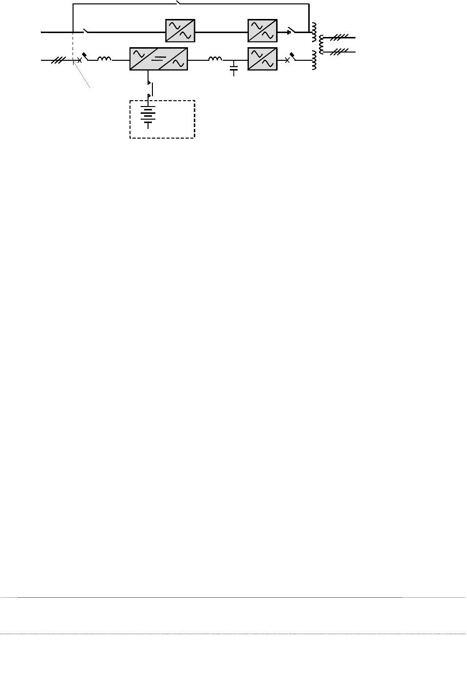
Figure 2 – Block diagram – 50/80kVA
The uninterruptible power system consists of the following:
1 - RECTIFIER/INVERTER S1 = Equipment ON/OFF switch
2 - BATTERY S2 = Equipment Reserve switch
3 - BACKFEED PROTECTION S3 = Equipment By-pass switch
4 - INVERTER STATIC SWITCH S4 = Equipment OUTPUT switch
5 - RESERVE STATIC SWITCH (INVERTER OUTPUT switch for 50/80kVA only)
S5 = RESERVE OUTPUT switch for 50/80kVA only
1.4 Functions
RECTIFIER / BATTERY CHARGER
The rectifier/battery charger transforms the alternating current of the mains supply to direct voltage to maintain the
battery in a fully charged state and also supply the inverter.
BATTERY
The battery is an energy reserve that is used by the inverter and the load whenever the mains supply fails.
INVERTER
The inverter changes the direct voltage from the rectifier or from the battery into a three phase sinusoidal alternating
voltage for the external supply.
ELECTRONIC STATIC SWITCH
The function of the electronic static switch is to select one of the two sources of alternating voltage and to supply it to the
external load. The two sources of voltage supplied to the static switch are the output of the inverter and the reserve
supply. In normal working conditions, the static switch supplies the load from the inverter.
SWITCHES
The switches permits maintenance and repair of the UPS, without interrupting the supply to the load.
3
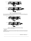
Maintenance Bypass
IN THE ABSENCE OF A SEPARATE
RESERVE SUPPLY THE RESERVE IS
DERIVED FROM THE AC UTILITY
INPUT WITH THE JUMPER
CONNECTED AS INDICATED
AC Supply
240 Cells
(External)
Battery
Contactor
1
S1
480V
S2
Reserve
Supply
S3
2
4
480Y/277V
S4
5
208Y/120V
S5