


page
64 --
MI00/10056 rev. 8 —05/2006
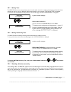
13.0 BATTERIES
13.1 EDP70 PLUS/24/18/12 : Battery Installation/Start-up
SAFETY
- Ensure all the Switches are turned to OFF before starting to install the batteries. If any Switches are not
turned to OFF the equipment and battery may be damaged. It is also essential for safety reasons that the
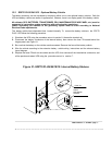
battery connectors be disconnected before removing the fuse F2 (located behind the hinged panel, see
Figure 31) to interrupt the battery circuit.
- Stand on a rubber mat and use insulated tools.
- Remove all personal effects, rings, watches, pens, which might cause a short circuit when working on
the battery. Batteries are live at all times and short circuits can melt metals and cause injury, damage or
fire.
- DO NOT smoke or use naked flames, and avoid creating arcs or sparks when working on the
equipment; do not wear clothes which may generate static electricity.
- The sealed lead-acid batteries contain sulphuric acid. If a battery container is broken any acid leaking will
cause burns on contact with skin and attack metal, paint and fabrics. Any area contaminated with acid
should be thoroughly washed with large volumes of clean water. Rubber gloves should be worn when
handling damaged batteries.
i) Remove front panel see figure 10
ii) Remove the battery compartment panel by unscrewing the fixing screws at the front.
DO NOT remove the safety ground connection. Battery connections are provided with the UPS. Each
battery is provided with fastenings.
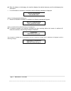
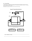
Internal batteries are housed on three shelves at the bottom of the equipment as shown on Figure 31.
If the batteries are fitted, starting with the lower shelf first, remove the packaging. Connect the batteries to the
UPS using the plug/socket connectors provided.
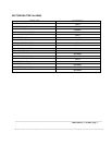
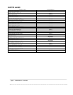
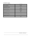
Starting with the lower shelf, fit and connect the batteries. Ensure that the polarities are correct in
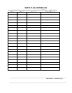
accordance with the relevant battery layout diagram.
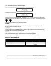
For each shelf make sure that the polarities are correct and the overall battery shelf voltage is at least 108v
for the bottom two shelves and 72v for the top shelf.
Replace the fuse F2, then connect the intershelves connectors and all panels in reverse order of removal
before operating the equipment.