


page
32 --
MI00/10056 rev. 8 —05/2006
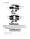
5.1 Electrical connections
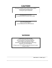
WARNING!
All electrical connections must
be made by a qualified electrician
and meet local electrical code standards
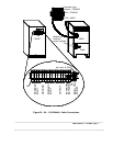
Before attempting to connect the mains supply, the reserve/bypass supply or the load, ensure that all supplies, including
the battery, are isolated and that all the equipment switches are in their »OFF» position.
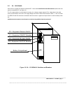
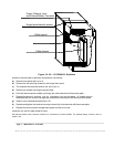
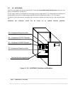
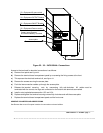
Open UPS front access panel and remove internal panel over main switches and terminal blocks.
NOTES:
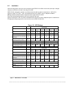
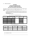
1) Installation must be performed by a qualified electrician. The terminals require the use of
the proper crimp tools and terminals in order to perform an installation in accordance with the
National Electrical Code (NEC). The recommended crimp tools, terminals and torque are shown
in the following tables:
2) Use Copper Conductors Only
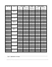
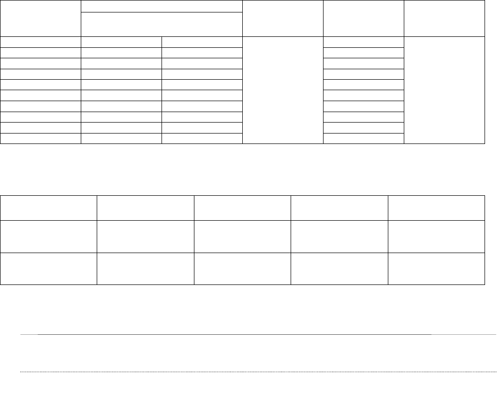
Table 1 – T&B’s Cat. N°s. for terminals and crimp tools
Terminals
Hole for screw
Wire
Size
(AWG)
M6 M10
Toggle
hand
Nest
(stationary)
tool
Indentor
(Moveable)
8 D10711 D975 11803
6 E10711 E975 11803
4 F10711 F975 11805
3 F10711 F975 11805
2 G971 G974 WT117 11806 11802
1 G671 G974 11806
1/0 H971 H974 11807
2/0 J971 J974 11808
3/0 K971 K974 11809
4/0 L971 L974 11810
Table 2 – Recommended torque
Torque Type Screw Wrench
(mm)
(Nm) (lb.in)
Used ON
Entrelec
M 35/26.FF
M6
10
4.5
39
EDP70Plus
up to 24kVA
-------
M10 17
39 340
EDP70Plus
above 24kVA