


MI00/10056 rev. 8 — 05/2006-- page
63
11.2 RS232
The EDP70 PLUS UPS is fitted with a 9 pin male ‘D’ type plug which enables a communication link to be established
between a computer and the microprocessor controller in the EDP70 PLUS UPS. The link allows the Chloride ‘EASY
PLUS’ and ‘LIFE 2000’ software to be run on an IBM compatible PC. The link also allows the communications with a
Master JBUS and Multicom/LIFE 2000 adapter.
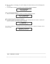
The function of the pins on the socket are shown below:
The function of each pin is the following :
Pin 1 DCD (Data Carrier Detect)
Pin 2 RXD (Received data)
Pin 3 TXD (Transmitted data)
Pin 4 DTR (Data terminal ready)
Pin 5 GND (Ground)
Pin 6 DSR (Data Set Ready)
Pin 7 RTS (Request To Send)
Pin 8 CTS (Clear To Send)
The signals applied on each pin follows the standard EIA RS232.
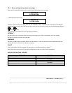
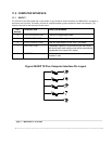
12.0 REMOTE ALARMS
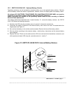
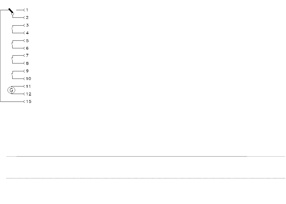
Remote indication of the state of the EDP70 PLUS UPS is provided by a 15 pin female ‘D’ type socket and is designed to
be used in conjunction with the Chloride EDP Remote Alarm Unit. The function of the pins on the socket are shown
below:
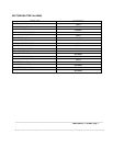
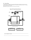
Figure 30 EDP70 PLUS Remote Alarms Pin Layout
Pin 1 System normal signal
Pin 2 System normal and system summary alarm ground
Pin 3 Inverter fail signal
Pin 4 Inverter fail ground
Pin 5 Reserve to load signal
Pin 6 Reserve to load ground
Pin 7 Primary supply failure signal
Pin 8 Primary supply failure ground
Pin 9 Shutdown imminent signal
Pin 10 Shutdown imminent ground
Pin11, 12 supply: 18V/200mA nominal AC output
Pin 15 Summary alarm signal
Pins 1,2 and15 are available for use as a remote summary alarm indicator in alternative to the Chloride
Remote Alarm Unit. All pins are volt free contacts which are capable of carrying a current of 0.5 A and
switching 30 V.