


page
6 --
MI00/10056 rev. 8 —05/2006
Figures
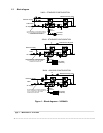
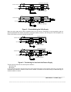
Figure 1 – Block diagrams – 24/36kVA
10
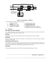
Figure 2 – Block diagram – 50/80kVA
11
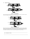
Figure 3 – Normal operation
12
Figure 4 – Utility Supply failure
12
Figure 5 – Re-establishing the Utility Supply
13
Figure 6 – Transferring the Load onto the Reserve Supply
13
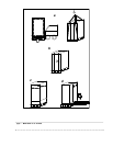
Figure 7 – 24 Footprint and cabinet dimensions
17
Figure 8 – 36 Footprint and cabinet dimensions
18
Figure 9 – 50/80 Footprint and cabinet dimensions
19
Figure 10 – “A” Battery Cabinet Drawing for 24/36kVA Ratings
20
Figure 11 – “B” Battery Cabinet Drawing for 24/36kVA Ratings
21
Figure 12 – “E” Battery Cabinet Drawing for 50/80kVA Ratings
22
Figure 13 – “F” Battery Cabinet Drawing for 50/80kVA Ratings
23
Figure 14 – “C” Battery Cabinet Drawing for 36/50/80kVA Ratings
24
Figure 15 – “D” Battery Cabinet Drawing for 50/80kVA Ratings
25
Figure 16 – UPS Ratings
26
Figure 17 – Connection diagrams
30
Figure 18 - 24 – 12/18/24kVA: Switches and Breakers
33
Figure 19 - 24 – 12/18/24kVA: Switches
34
Figure 20 - 24 – 12/18/24kVA: Cable Connections
35
Figure 21 - 36 – 24/30/36kVA: Switches and Breakers
36
Figure 22 - 36 – 24/30/36kVA: Connections
37
Figure 23 - 36 – 24/30/36kVA: Cable Connections
38
Figure 24 – 50/80kVA: Switches and Breakers
39
Figure 25 – 50/80kVA: Connections
40
Figure 26 – 50/80kVA: Cable Connections
41
Figure 27 – Control panel
43
Figure 28: Power History Structure
60
Figure 29 EDP 70 Plus Computer Interface Pin Layout
62
Figure 30 EDP70 PLUS Remote Alarms Pin Layout
63
Figure 31- EDP70 PLUS/24/18/12: Internal Battery Shelves
65