


page
40 --
MI00/10056 rev. 8 —05/2006
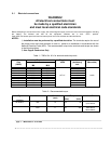
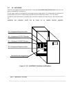
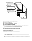
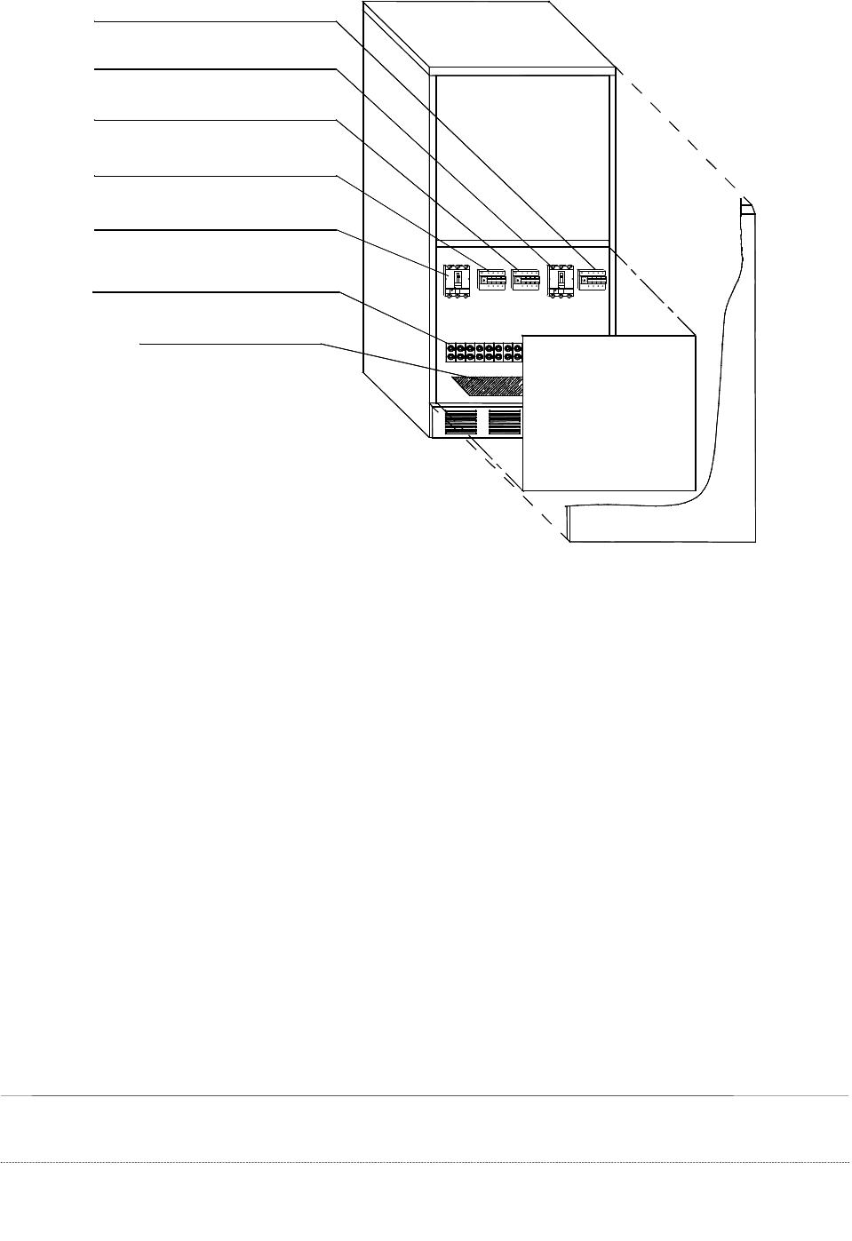
Figure 25 – 50/80kVA: Connections
Access to the terminals for electrical connections is as follows:
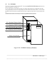
a) Remove front panel see
Figure 22
.
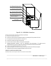
b) Remove the terminal board compartment panel by unscrewing the fixing screws at the front.
e) This exposes the electrical terminal rail, see
Figure 23
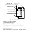
f) Remove the screws securing the access plate.
e) Push the interconnection cables up through the access plate.
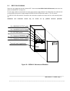
f) Release the terminal securing nuts by unscrewing fully anti-clockwise. All cables must be terminated with
the correct size lugs and connected on the bottom side terminals as marked.
g) Install or start-up batteries see section 13.3 and 13.4.
h) Replace and tighten the terminal securing screws fully clockwise and refit the access plate.
i) Replace the terminal board compartment panel and the front cover.
OBSERVE POLARITIES AND ORIENTATIONS.
See Remote Alarms and Computer Interface for connections to these facilities.
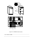
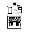
Output, Input, Reserve
and External Battery Terminals
Access plate
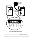
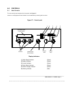
S5 = RESERVE OUTPUT switch
S3 = BY PASS switch
S2 = Equipment RESERVE switch
S4 = INVERTER OUTPUT Breaker
S1 = Equipment ON/OFF Breaker