


Magnum 8000X Mixed-Media Fiber Hubs Installation and User Guide (05/ 02)
22
www GarrettCom com
..
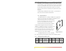
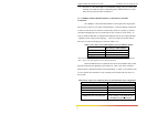
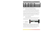
The various media types supported along with the corresponding IEEE
802.3 and 802.3u standards and connector types are as follows:
IEEE Standard Media Type Max. Distance 8000X Port Module
Fiber:
10BASE-FL mm
1
Fiber 2.0km(6562 ft) FPM10-MST, FPM10-MSC
sgl.m
2
Fiber 10.0km(65620ft) FPM10-SST, FPM10-SSC
100BASE-FX mm
1
Fiber 200 m
3
(650 ft) FPM-MSC, FPM-MST
small form factor “ “ FPM-MTRJ, FPM-MV45
sgl.m
2
Fiber 200 m
3
(650 ft) FPM-SSC
100BASE-SX (proposed, 850nm mm
1
) 150 m
3
(500 ft) FPM-SXMST, -SXMSC -
short wavelength
Copper:
10BASE-T & 100BASE-TX twisted pair 100m (328 ft) PM-RJ45, PM-RJ45U
1
mm = multi-mode
2
sgl.m = single-mode
3
max. each for two segments in a 100Mb collision domain. Single segment is 412m for FX and 300m for
SX.
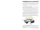
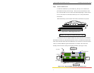
3.3 Connecting Fiber Optic ST-type, “twist-lock”
The following procedure applies to installations using an PM with
ST-type fiber connectors. This procedure applies to ports using an FPM-MST,
FPM10-MST, FPM10-SST single-mode, FPM-SXMST, and to SPM-FDST.
1. Before connecting the fiber optic cable, remove the protective dust caps from
the tips of the connectors on the FPM. Save these dust caps for future use.
2. Wipe clean the ends of the dual connectors with a soft cloth or lint-free lens
tissue dampened in alcohol. Make certain the connectors are clean before
connecting.
Note: One strand of the duplex fiber optic cable is coded using color
bands at regular intervals; you must use the color-coded strand on the
associated ports at each end of the fiber optic segment.
3. Connect the Transmit (TX) port (light colored post) on the Magnum FPM to the
Receive (RX) port of the remote device. Begin with the color-coded strand of
the cable for this first TX-to-RX connection.
4. Connect the Receive (RX) port (dark colored post on the PM) to the Transmit
(TX) port of the remote device. Use the non-color coded fiber strand for this.
5. The LINK LED on the front of the PM will illuminate when a proper connection
has been established at both ends (and when power is ON in the unit). If LINK
is not lit after cable connection, the normal cause is improper cable polarity.
Swap the fiber cables at the Port Module connector to remedy this situation.
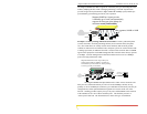
3.4 Connecting Fiber Optic SC-type, "Snap-In"
The following procedure applies to installations using an PM with SC-type
fiber connectors. This procedure applies to ports using an FPM-MSC, FPM-SSC single-
mode, FPM10-MSC, FPM10-SSC, FPM-SXMSC, and to SPM-FDSC and -FDSSC
single-mode.