


Magnum 8000X Mixed-Media Fiber Hubs Installation and User Guide (05/ 02)
34
www GarrettCom com
..
SPM card installation is covered in Section 3.10.1, PM card removal in Sect3.10.2.
3.10.1 Installing an SPM Module in the Magnum 8000X
There is only one SPM module may be installed in the Magnum 8000X Fiber
Hub unit. The SPM bonus port slot is accessible on the rear of the unit
Follow these steps to install an SPM.
Step 1. Remove top chassis cover. See procedure in Section 3.10a above.
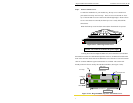
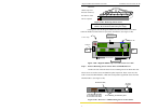
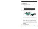
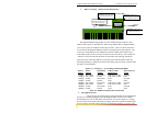
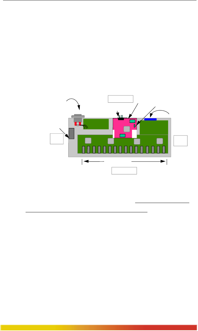
Step 2. The figure 3.10.1a below illustrates the layout of an SPM module installed in
a 8000X unit. The SPM module fits easily into the SPM header.
Fig. 3.10.1a Top View : SPM Module Installed in a 8000X
Align the 40-pin male header on the main board of the Magnum 8000X with
the female sockets on the SPM module carefully. Any misalignment of the
pins will prevent proper functioning of the SPM module.
Step 3. Slowly and firmly push the SPM into position. Once inserted, the SPM card
is then secured by the header connector. Re-insert the retaining screws on the
SPM module cover plate to provide stability .
NOTE: The SPM Bonus Port slot need not be populated in order for the
Magnum 8000X unit to be operational. When leaving SPM slots empty, always
use a face plate (supplied and factory-installed in all non-SPM units)) to cover
the slot opening in the rear panel. This will maintain proper cooling air flow for
safety, and operation as required by FCC, CE, and other regulations.
Step 4. Once SPM card has been installed, the user can adjust the jumper settings
either to half or full duplex. The SPM module, by default, comes with half-
duplex settings. Finally the chassis cover should be replaced and screwed
down.
Inter-Repeater Bus
AC Power Input
Sixteen PM Slots
Back of Unit
Front of Unit
Right
Side
Left
Side
SPM Bonus Slot
Cooling Fan
Power Supply Board
SPM Module installed
Jumper Settings For Half/Full duplex