


Magnum 8000X Mixed-Media Fiber Hubs Installation and User Guide (05/ 02)
46
www GarrettCom com
..
and with no cable connected. The FX port emits light outside of the visible spectrum
and will always look dark to the human eye.
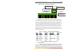
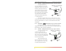
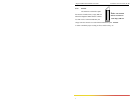
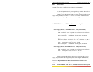
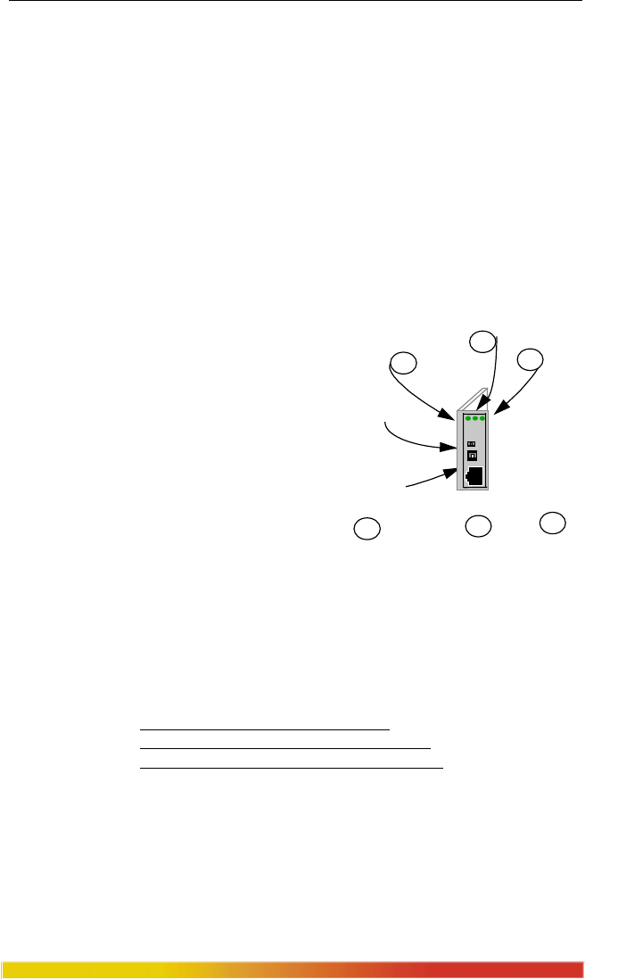
5.2.7 PM-RJ45 and RJ45U (Twisted Pair)
The PM-RJ45 card supports Ethernet twisted pair segments of any standard
length. It is equipped with a single RJ-45 connector and an Auto/100 switch. The RJ-45
connector is shielded to minimize emissions and will allow both unshielded twisted pair
(UTP) and shielded twisted pair (STP) cable connections. The Auto/100 switch is
provided for user selection between operation in the auto-negotiation mode (Auto) or
fixed-at-100Mb (100) with no auto-negotiation and no 10 Mbps.
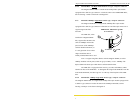
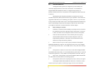
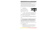
The PM-RJ45U module is equipped with a Media Dependent Interface-
Crossover (MDI-X) push switch to allow for cascaded connections. This feature
eliminates the need for a special twisted
pair crossover cable.
With the switch in the IN
position, the PM-TP port is used for
cascaded and up-link connections (i.e.: a
connection to another repeater or hub or
concentrator typically.) When used for
segments going to workstations and
other user device connections, the MDI-
X switch should be in the OUT position.
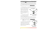
The PM-RJ45 will support 10BASE-T unshielded twisted pair wiring (UTP)
environments with maximum segment distances up to 100m (325 ft.), or shielded
twisted pair wiring (STP) of 150m (500 ft.). This module is designed with internal
transceiver functionality. The PM-RJ45 has ACTIVITY, LINK and SPEED LEDs.
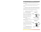
Important Note: For the PM-RJ45U Crossover Switch -
OUT for workstations and user connections.
IN for Up-Link connections to other hubs, etc.
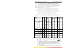
The RJ-45 pins normally (TP crossover switch DOWN) are per the
standard for hubs-to-users twisted pair wiring: 1 = receive+, 2 = receive-,
3 = transmit+, 6 = transmit-, other pins not used. When the TP crossover
switch is UP, the pins of the RJ-45 port are per the standard for up-links
using twisted pair wiring, i.e., the transmit and the receive pairs are
exchanged: 1 = transmit+, 2 = transmit-, 3 = receive+, 6 = receive-, other
pins not used.
1
ACTIVITY
SPEED
2
3
LIN
K
Shielded RJ-45
Connector
Auto/100 Switch
1
2
3
RJ45U
Cross-Over
Push Switch
PM-RJ45U
1
ALS