


Magnum 8000X Mixed-Media Fiber Hubs Installation and User Guide (05/ 02)
30
www GarrettCom com
..
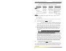
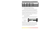
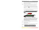
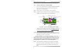
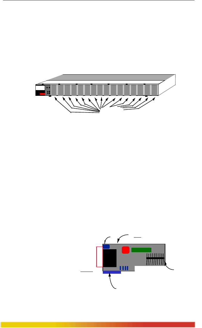
Step 2. Remove bottom-front Retaining Screws in any PM or Face Plates
On the bottom-front of the unit, there is one retaining screw for each PM card slot.
These screws are used to secure a PM face plate in position. These screws are also used
to secure the individual PM cards, which can be subjected to significant forces from the
attached cables. (See Figure 3.9.1c)
Figure 3.9.1c: Front View - PM Retaining Screws hold Face Plates
PM card installation is covered in Section 3.9.2. PM card removal is covered in
Sect.3.9.3.
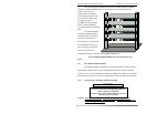
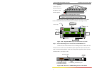
3.9.2 Installing PM Cards in the Magnum 8000X
Up to sixteen front-mounted PM cards may be installed in one Magnum
8000X Fiber Hub unit. Follow these steps to install a PM.
Step 1. Remove front-top chassis cover. See procedure in Section 3.9.1 above.
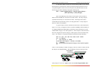
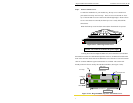
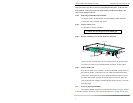
Step 2. The figure here
illustrates the basic
layout of an
individual PM card.
Each PM card fits
into the selected PM
connector socket
slot. Align the
BOTTOM-Front PM
Retaining Screws
10100
PWR
BRD
ACT
COL
Magnum 8000X
Mixed Media Hub
GARRETT
1
Bottom PM Retaining
Screw Hole
Ten(10) Pin
PM Connector
(inserts into main board
)
Printed Circuit card
FRONT
TOP
LED