


Magnum 8000X Mixed-Media Fiber Hubs Installation and User Guide (05/ 02)
33
www GarrettCom com
..
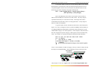
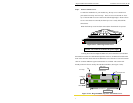
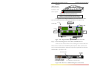
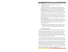
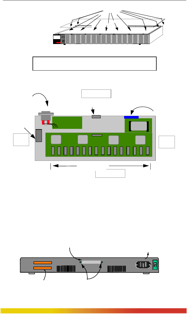
When the
chassis top cover
has been removed,
the interior of the
unit is exposed.
Figure 3.10a: Removing Chassis Cover
Caution: Be sure the power cord is unplugged.
Caution: Be careful not to disturb the power supply.
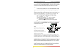
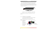
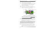
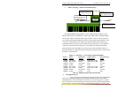
Looking down into the Magnum 8000X unit, notice that there is one SPM
connector header located on the rear part of the main board. (See Figure 3.10b).
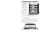
Figure 3.10b: Magnum 8000X, Top View with Chassis Cover Off
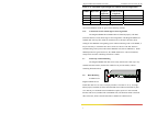
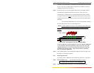
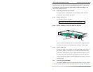
Step 2. Remove Retaining Screws in Face Plates of SPM Bonus Port
On the rear side of the unit there are two retaining screws for Bonus Port slot.
These screws are used to secure an SPM face plate in position. These screws are also
used to secure the SPM modules, which can be subjected to significant forces from the
attached cables. (See Figure 3.10c)
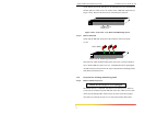
Figure 3.10c: Rear View - SPM Retaining Screws in Face Plates
10100
PWR
BRD
ACT
COL
Magnum 8000X
Mixed Media Hub
GARRETT
1
TopChassis Cover
20 Phillips Head
Screws on Top
Front of Unit
Media Connector
with electronic elements
Inter-Repeater Bus
AC Power Input
Sixteen PM Slots
Back of Unit
Right
Side
Left
Side
SPM Bonus Slot
Cooling Fan
Power Supply Board
Bridge
Inter-Repeater Bus (IRB)
P3 - Interface to unit above.
P4 - Interface to unit below.
AC Power
Connector
Bonus Port Slot,
1 8
OUT
IN
ON
OFF
Screw Holding the SPM face plate