


Magnum 8000X Mixed-Media Fiber Hubs Installation and User Guide (05/ 02)
31
www GarrettCom com
..
connector pins on the bottom of the PM card with the connector socket inside
the unit. The pins are slightly angled to facilitate the installation. (Do NOT
straighten the pins before insertion !!)
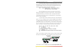
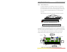
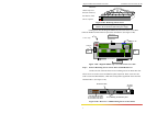
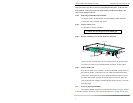
Step 3. Be sure the pins are precisely aligned with the holes in the header, and the
PM front panel is guided into the front slot cut-out. Then, slowly and
carefully apply enough pressure to insert the PM card’s pins into position,
see Figure 3.9.2b. (If you force the PM down when the pins are not properly
aligned with the holes in the header, the pins will become bent and the PM is
damaged).
Once inserted, the PM card will be secured by the header connector,
the front panel port slot cut-out, and retaining screws.
NOTE: If a PM is difficult to install, try it in another port slot. Some of the
port modules may fit easily in one port slot and be very hard to install in
another.
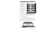
Figure 3.9.2b: Inserting PM Cards into a Magnum 8000X
NOTE: All PM slots need not be filled in order for the Magnum 8000X unit
to be operational. When leaving PM slots empty, always use a face plate
(Magnum PM-FP) to cover the slot opening in the front panel. This will
maintain proper cooling air flow, safety, and operation as required by
FCC, CE, and other regulations.
Step 4. Once all PM cards have been installed (including face plates for empty slots),
the chassis cover should be replaced.
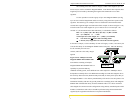
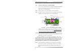
3.9.3 Removing PM Cards
To properly remove a PM card from the Fiber Hub, follow the 3 steps below.
Step 1. Remove chassis cover See procedure in Section 3.9.1 above.
Caution: Be sure the power cord is unplugged.
Step 2. Remove bottom-front retaining screws for the PM and Face Plate
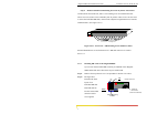
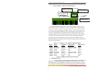
10100
PWR
BRD
ACT
COL
Magnum 8000X
Mixed Media Hub
GARRETT
1
PM CARDS