


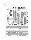
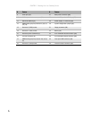

CHAPTER 1: Checking Out Your Gateway Server
8
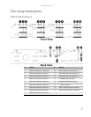
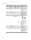
LED information
See the following table for a description of this server’s LEDs and the information they provide:
LED Name Function Location Color Description
ID Aid in server
identification
Control panel and
back of system
board
Yellow
(front)
Blue (back)
On = Server identification
enabled
System Fault Visible fault
warning
Control panel Red Off = System normal
Blinking = Non-critical system
fault
On = Critical system fault
(system needs to be shut down
and serviced)
Hard drive tray
LEDs
Indicate drive
status and activity
On each hard drive
tray
Blue or red Blue (On) - Hard drive present
Blue (Blinking) - Hard drive
activity
Red (On) - Hard drive fault
Red (Blinking) - Hard drive
rebuilding
Off - No hard drive access
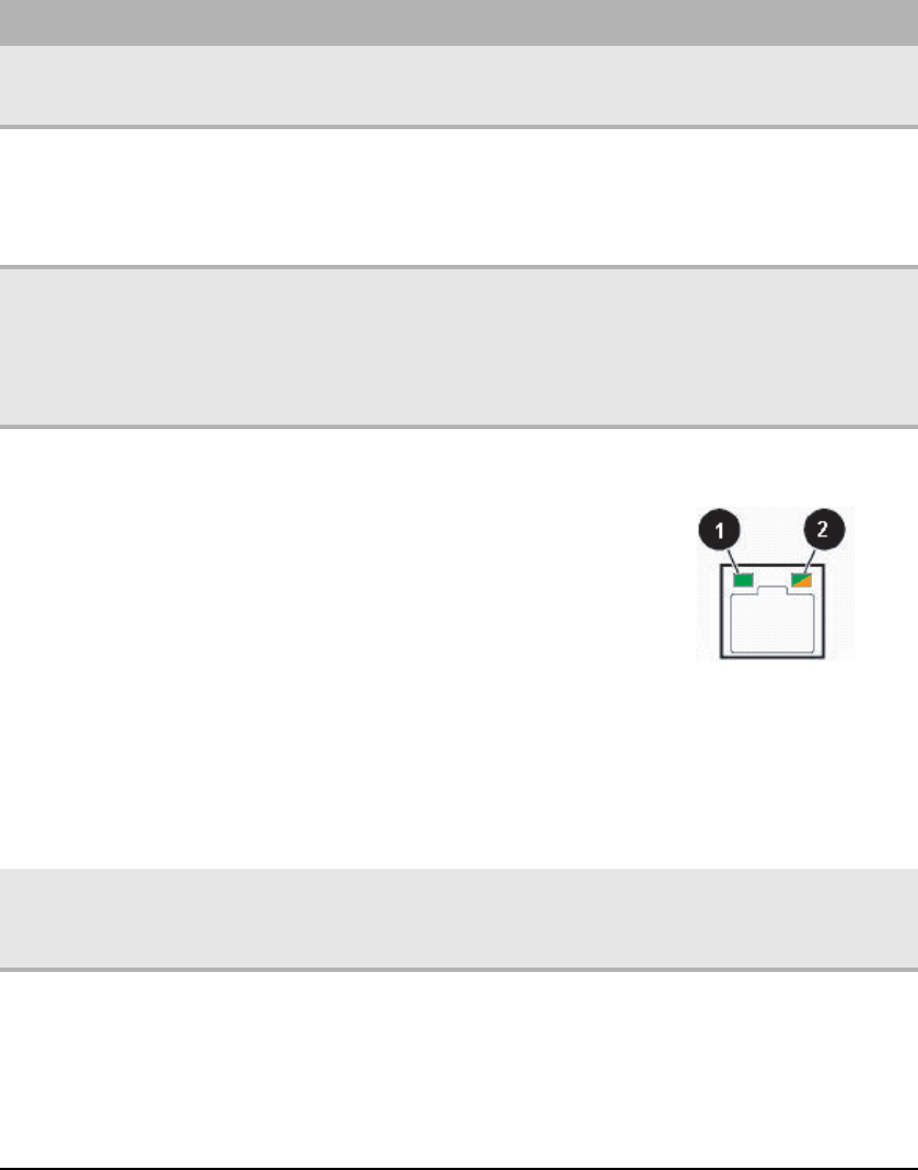
NIC status LEDs Identify NIC states Control panel and
back I/O panel
RJ-45 connectors
Blue (front)
Green/
Orange
(back)
Blue (On) - Link
Blue (Blink) - Activity
Off - No link
LED 1 Green (On) - NIC linked
LED 1 Green (Blinking) - NIC
1 Gbps activity
LED 1 (Off) - No link
LED 2 Orange (On) Link speed
1Gbps
LED 2 Green (On) - Link at
100 Mbps
LED 2 Green (Off) - Link at
10 Mbps
Power LED Identify the power
state of the system
Control panel Blue Off = Power is off
Blinking = Power saving state
(S1, S3, or S4)
On = Power is on
AC power LED Identify power
supply fault
Power supply
module
Green or
Orange
Green (On) - Power supply good
and receiving power
Orange (On) - Power supply
critical event causing shutdown
Orange (Blinking) - Close to
protection threshold or over
within 15 seconds
Off - Power supply not receiving
power