


GBC 4064WF-1 Operation Manual
© 2009 GBC an ACCO Brands Co. Page 13
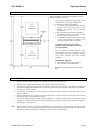
FEATURES/ACCESORIES GUIDE
Refer to the following pages for detailed information on the
Features
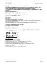
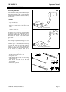
FIGURE A
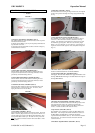
1. Emergency Stop Buttons: (FIGURE A, Item 1)
Four E-Stop buttons are on the Laminator located on the top of the
Laminator at all four corners.
To Engage E-Stop buttons, press any E-Stop Safety Push button to
stop the roller movement.
To disengage turn the push button clockwise when the emergency
condition has been resolved.
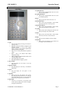
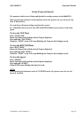
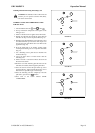
FIGURE B
1. Heated Main Top Roller: (FIGURE B, Item 1)
Silicone rubber coated steel tube heat the laminating film and
compress the heated film to the items being laminated. Heat is
provided by an internal heating element.
2. Heated Main Bottom Roller: (FIGURE B, Item 2)
Silicone rubber coated steel tube heat the laminating film and
compress the heated film to the items being laminated. Heat is
provided by an internal heating element.
3. Media Pressure Plate: (FIGURE B, Item 3)
The Pressure Plate mounted to the front of the table helps hold
down the image as it enters the Nip Area. To remove, move
Spring Pin, and remove Pressure Plate.
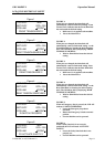
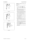
FIGURE C
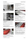
1. Front Table: (FIGURE C, Item 1)
The Front Table aids the operator when aligning media. The Front
Table is stationary but pivots down for easy access to the film. To
pivot the table down, lift up on the Media idler (FIGURE C, Item
2) and pull the table towards you. The table can now pivot down.
Note:
The machine is limited to 3ft/min while either table is in the
down position.
2 Table Idler: (FIGURE C, Item 2)
The Table Idler assists feeding of images into the web. It is helpful
in roll to roll operation and helps move large rigid panels through
the nip.
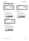
FIGURE D
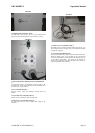
1. Safety Light Beam System: (FIGURE D, Item 1)
The 4064WF-1 uses a Safety Light Beam to protect the end-user
from harm. When this Beam is blocked, the Rollers will stop
rotating. Once the Beam is interrupted, the operator must re-start
the machine by pressing Run. There are 2 sets of Safety Light
Beams. One set in the front, one set in the rear. (See Sequence of
Operation Chart for detail sequence of the Safety Beam. Diagram 1
Page 11)
FIGURE E
1. Rewinder Tubes: (FIGURE E, Item 1)
Used to rewind release liners or finished Medias.
2. Upper Tension Idler Bar: (FIGURE E, Item 2)
The Upper Tension Idler Guides the upper lamination onto
the Top Main Roller insuring a constant amount of wrap on
the Top Main Roller.
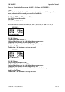
FIGURE F
1. Rewinder Clutch Adjustment: (FIGURE F, Item 1)
The 4064WF-1 has Rewinder Tubes that will take-up release liners
and rewind finished product. By rotating the gnarled disk
(FIGURE F, Item 1) Counter Clockwise, the take up action will
increase. Counter Clockwise will reduce the effect.
2. Nip Pressure: (FIGURE F, Item 2)
The 4064WF-1 uses pneumatics to operate the Main Rollers and
Pull Rollers. You can adjust the amount of PSI that is desired on
the Main Rollers and Pull Rolls by rotating the Pneumatic
Adjustment Knob (FIGURE F, Item 3). To increase PSI, rotate the
knob cock-wise. To reduce the amount of PSI, turn the knob
counter clock-wise.
3. Pneumatic Adjustment Knob: (FIGURE F, Item 3)