


GBC 4064WF-1 Operation Manual
© 2009 GBC an ACCO Brands Co. Page 15
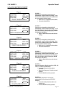
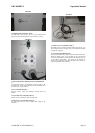
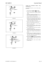
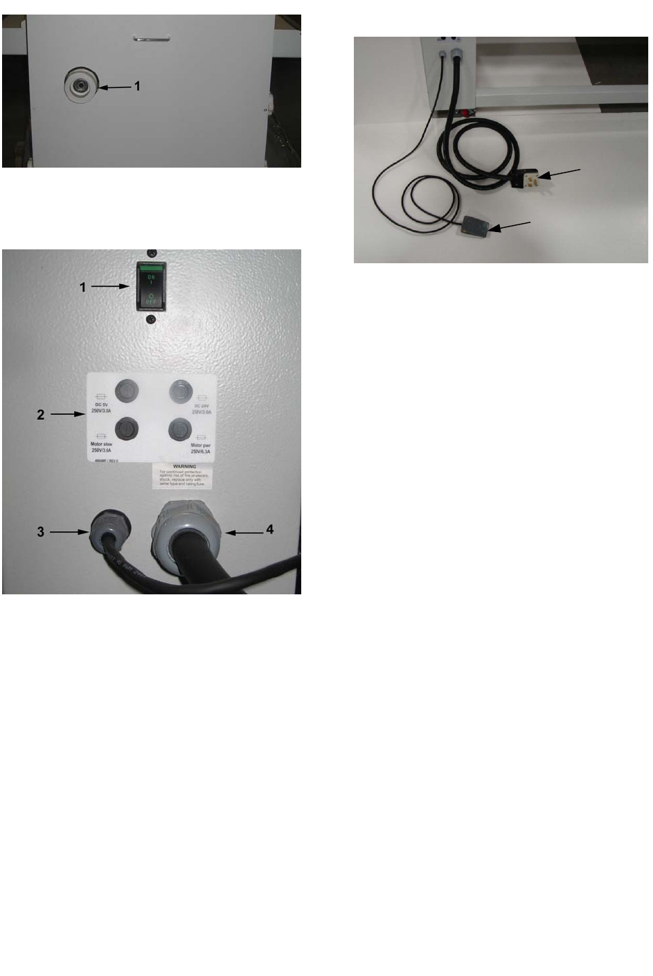
FIGURE L
1. Pull Roll Clutch: (FIGURE L Item 1)
The Pull Roll Clutch provides tension on the laminated film
between the main rolls and pull rolls as the material is cooling.
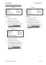
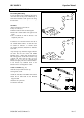
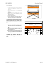
FIGURE M
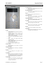
1. Main Circuit Breaker/ ON/OFF Switch: (FIGURE M Item
1)
To apply Main Power to the Laminator, Press the switch to the
“ON” Position. To disconnect Main Power to the Laminator, press
the switch to the “OFF” position.
2. Fuses: (FIGURE M Item 2)
There are 4 fuses. Each one is labeled to describe each fuses
function.
3. Foot Switch Cord: (FIGURE M Item 3)
The Foot Switch is attached to the Footswitch cord.
4. Main Power Cord: (FIGURE M Item 4)
The main Power Cord is used to supply Main voltage to the
Laminator.
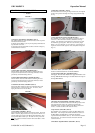
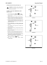
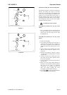
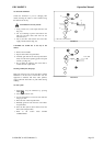
FIGURE N
A
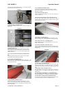
B
1. Main Power Cord. (FIGURE N Item A)
The Main Power Cord Plugs into the Main Power Supply. See
Power Requirements in the Specs part of the manual for required
Voltage and Amperage.
2. Foot Switch. (FIGURE N Item B)
The Foot Switch allows the operator to run the machine hands free.
When the PICO System is not blocked, the Foot Switch will
activate the Main Rollers, and the machine will run at the set speed
on the Main Control Panel. The Speed can be adjusted by
selecting the Speed button and using the Main Dial to increase or
decrease speed while unit is running.