


GBC 4064WF-1 Operation Manual
© 2009 GBC an ACCO Brands Co. Page 14
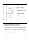
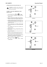
To increase PSI, rotate the knob cock-wise. To reduce the amount
of PSI, turn the knob counter clock-wise.
FIGURE G
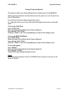
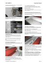
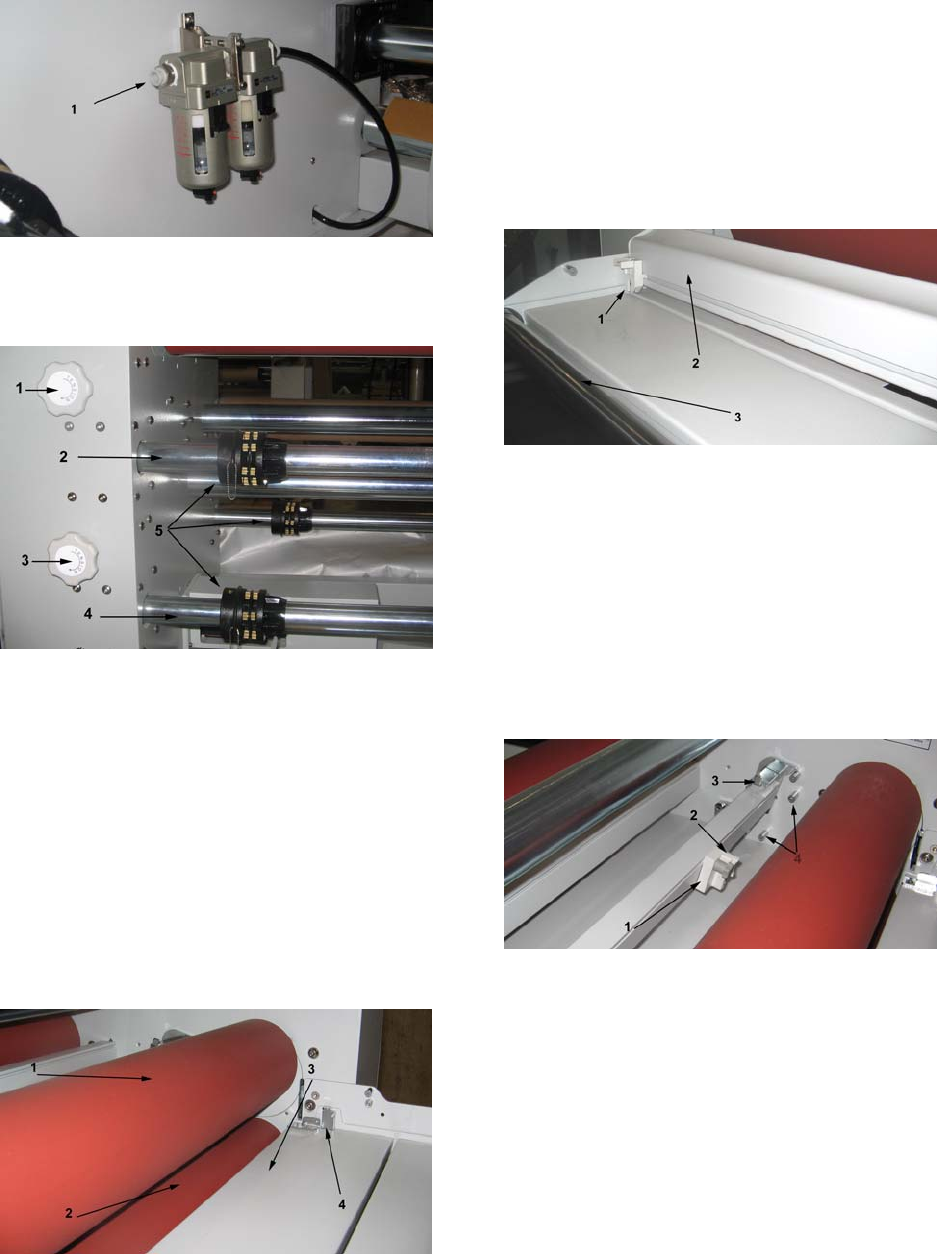
1. Main Air Supply: (FIGURE G, Item 1)
The 4064WF-1 requires Compressed Air. Connect to the Main Air
Supply at #1.
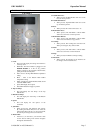
FIGURE H
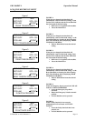
1 & 3. Swing -Out Film Unwind Shaft Brake Tension Knob:
(FIGURE H, Item 1 & 3)
The Swing-out Film Shaft is used to provide tension to match
materials going into the laminated rollers. To increase tension,
rotate the knob clock-wise. To reduce tension, rotate the knob
counter clock-wise
2 & 4. Swing -Out Film Unwind Shaft: (FIGURE H, Item 2
&4)
The Swing-out Film Shaft is used to provide tension to match
material when holding media and materials.
5. Core Chucks: (FIGURE H, Item 5)
Bi-Directional Core Chucks grip the Medias supply tube. Our
patented roller core chuck will allow the operator the ability to add
or remove film with ease.
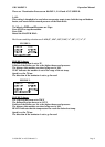
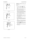
FIGURE I
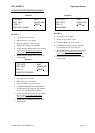
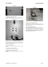
1. Upper Pull Roll: (FIGURE I, Item 1)
The Pull rollers located at the back of the laminator are motor
driven. They simultaneously pull the film and image. The Upper
Pull Roller (FIGURE I, Item 1) can be Raised and Lowered via the
Main Control Panel.
2. Lower Pull Roll: (FIGURE I, Item 2)
The Pull rollers located at the back of the laminator are motor
driven. They simultaneously pull the film and image. The Lower
Pull Roller is clutched.
3. Rear Table: (FIGURE I, Item 3)
Used to support finished Media and used when running the
machine from the rear.
4. Rear Table Safety Interlock Switch: (FIGURE I, Item 4)
The Rear Table Safety Switch ensures that the Rear Table is
inserted properly and if not engaged, the machine will only operate
with the foot switch at 3ft/mn.
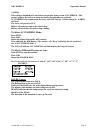
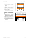
FIGURE J
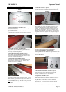
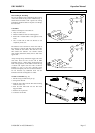
1. Rear Slitter: (FIGURE J, Item 1)
The Rear Slitter is used for slitting Media after lamination. Press
down on the Slitter Assy’ (FIGURE J, Item 1) to engage the slitter.
2. Rear Slitter Track Assy’: (FIGURE J, Item 2)
The Rear Slitter Track Assy’ allows the Slitter Assy’ to travel the
length of the Rear Table.
3. Rear Table Media Idler: (FIGURE J, Item 3)
Used for guiding Media through the laminator. The table Idler is
helpful in roll to roll operation and helps move large ridged panels
through the nip.
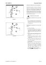
FIGURE K
1. In-Line Slitters: (FIGURE K, Item 1)
The In-Line Slitters allows the operator to slit images as they pass
through the Main Rollers and into the Pull rollers. The trimmed
waste can then be attached to the Rewinder Tubes and disposed of
later.
2. Slitter Blade Switch: (FIGURE K, Item 2)
The Slitter Blade can be engaged by pressing down carefully on
the Blade Switch. To disengage, carefully pull up on the Slitter
Blade Switch.
3. In-Line Slitter Bar Mounting Lever: (FIGURE K, Item 3)
The In-Line Slitters bar mounting Lever Allows the operator to
remove the Slitter Bar Assy’ or position it to the desired location.
4. In-Line Slitters Cutting Position: (FIGURE K, Item 4)
To lower the position of the In-Line Slitter Bar, release the Lever
and relocate to the position shown in FIGURE K Item 4.