Operations Manual Polaris II
Page 5-1 © 2004 General Binding Corporation
5.0 Operation
This section covers the components of the laminator, the
control panel, feed table, supply shaft, knife assembly film
alignment and tension knobs.
5.1 Components on the laminator
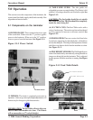
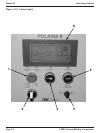
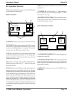
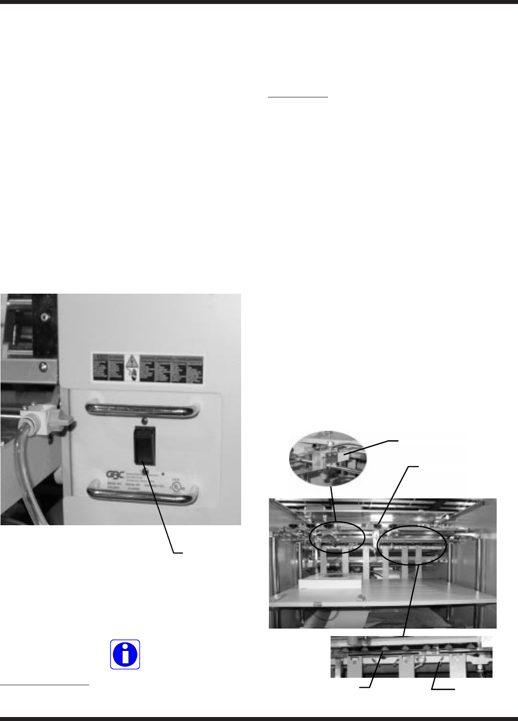
(1) POWER ON/ OFF: This is located to the lower right
of the catch table. When set to the “I” position, applies
power to the laminator. When set to the “O” position,
removes power from the laminator. See Figure 5.1.1.
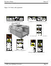
Figure 5.1.1 Power Switch
POWER SWITCH
(2) FEEDER : The feeder is completely automatic in
operation. After set up, minor pile height adjustments will
be necesary for changes in pile characteristics.
INFORMATION: The feed table will only allow one
sheet to enter the machine at a time. The Polaris
will accommodate an 17 inch pile height.
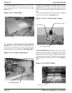
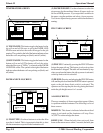
(3) TABLE SIDE GUIDE: The side guides are
adjustable to ensure accurate feeding. The Polaris is left
justified All settings should be set from left to right. See
Figure 5.1.2.
CAUTION: The feed guide should be set outside
the width of the film. The film should be completely
inside the sheet being fed.
(4) SUCTION CUPS: The Feed Table works with a
series of suction cups. The suction cup bar can be adjusted
to allow operator to increase or decrease suction. See
Figure 5.1.2.
(5) PILE BLOWER: There are a series of air blow holes
located on a support bar for the infeed plate, which blows
air into the sheet pile. This helps in the separation of sheets
and allows one sheet to be fed into the machine at a time.
See Figure 5.1.2.
(6) PILE HEIGHT SENSORS: The Pile Height Sensors
control the feed table by automatically raising the table as
images are being fed into the laminator. This is adjusted
by the operator while the machine is running. See Figure
5.1.2.
Figure 5.1.2 Feed Table Details
PILE HEIGHT SENSOR
SUCTION CUPS
PILE BLOWER
TABLE SIDE GUIDE


