


Operations Manual Polaris II
Page 5-9 © 2004 General Binding Corporation
alarm will activate and the laminator will stop.
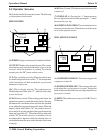
TOP HEAT SENSOR BLOCKED - When the top
heat sensor is blocked for more than 5 seconds, this alarm
will activate. When the alarm is displayed, the heat
automatically shuts off and must be manually reset.
BOTTOM HEAT SENSOR BLOCKED - When the
bottom heat sensor is blocked for more than 5 seconds,
this alarm will activate. When the alarm is displayed, the
heat automatically shuts off and must be manually reset.
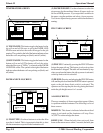
COVER ALARMS - There are 5 cover alarms. Feeder
Cover, Laminator Cover, Draw Cover, Cutter Cover and
Tension Roller. When the start button is pressed with a
cover open, this alarm will activate. The operator can
either accept the alarm or close the cover.
E-STOP ALARM - When the start button is pressed
with an E-STOP button activated, this alarm will display.
Reset the E-STOP to continue operation.
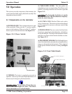
5.4 Supply Shaft
To remove film
1.
. Release any tension from the supply shaft.
2. Unscrew the Support Locking Pin Knob until the Film
Supply Shaft is free.
3. Gently lower the film support arm.
4. Loosen and remove core chuck end.
5. Remove film at this time.
To replace
1.
Slide the film over the supply shaft adhesive side away
from the roller.
2.Tighten core ends to secure film on supply shaft.
3. Raise the film support arm.
4. Screw in the Support Locking Pin Knob until the locking
pin is secured into the film supply shaft.
5. Spin roll to insure smooth rotation.
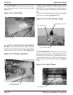
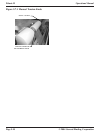
5.5 Separator Knife:
The integrated sheet separator is able to run with continuous
web flow for high production output. The precision knife
separates sheets while lamination web is moving.
INFORMATION: The laminator will operate only
when the knife separator, pull roll, decurling bar, film
tension roller and feeder shields are in their closed
position and the safety interlock latch is properly
engaged. Power to the motor is removed when any
safety shield is in the open position.
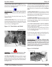
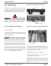
5.6 Film Alignment
The Polaris laminator is a left justified machine. Film should
be aligned from the left going to the right. Film should not
be centered on the supply shaft.
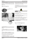
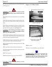
5.7 Film Tension
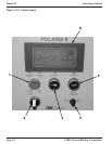
On the Operator Control Panel, use the Film Tension Knob
to adjust the amount of brake tension applied to the Film
Idler Roller. Clockwise will increase the brake. Counter-
clockwise will decrease the brake. Refer to Section 5.2
Control Panel for information on setting the film tension.
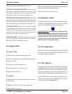
If the Film Idler Roller is not providing enough film tension,
additional tension can be set using the manual tension knob
on the supply shaft. See Figure 5.7.1.