Page 5-4 © 2004 General Binding Corporation
Operations ManualPolaris II
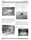
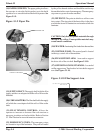
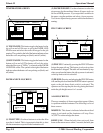
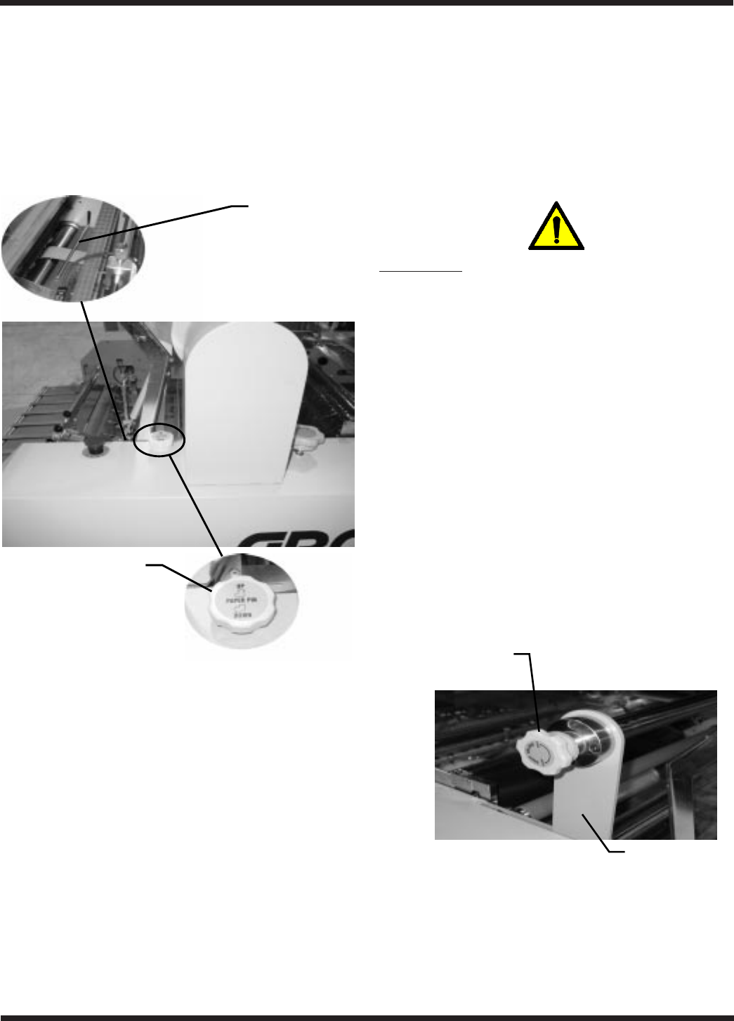
(18) PAPER GUIDE PIN: The paper guide pin allows
the operator to raise the finish product up to the knife
separator for a smooth feed into the knife separator. See
Figure 5.1.9.
Figure 5.1.9 Paper Pin
PAPER PIN
PAPER PIN KNOB
(19) SUPPLY SHAFT: The supply shaft holds the film
supply and the core adapters hold the rolls of film on the
film shaft.
(20) CORE ADAPTERS: The film shaft holds the supply
roll while the core adapters hold the rolls of film on the
shaft.
(21) FILM TENSION CONTROL: Allows the
operator to increase or decrease film web tension as
necessary to reduce curl and wrinkles. Refer to Section
5.2 Film Tension for more information on tension.
(22) EMERGENCY STOPS: The emergency stops
are located on top of the laminator. They can be located
by the yellow hazard stickers and should be used to stop
the machine in the event of an emergency. The emergency
stop removes power from the machine.
(23) NIP POINT: The point at which two rollers come
into contact. The nip point of the heat rollers is the place
at which the items for lamination are introduced into the
laminator.
CAUTION: Only feed acceptable materials through
the nip of the rollers. Unacceptable materials may
create unsafe conditions.
(24) FILM WEB: Laminating film loaded into the machine
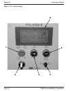
(25) CONTROL PANEL: The control panel is located
on the top, control side of the machine.
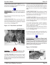
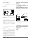
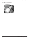
(26) FILM SUPPORT ARM: Arm used to support
the drive side of the air shaft. See Figure 5.1.10.
(27) SUPPORT LOCKING PIN KNOB: Locateded
on film support arm. Turn knob to lock air shaft to support
arm. See Figure 5.1.10.
Figure 5.1.10 Film Support Arm
FILM SUPPORT
ARM
SUPPORT LOCKING
PIN KNOB


