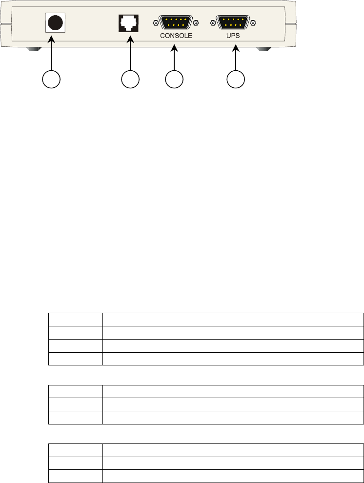
1 3
Rear
View
6
7
• 1 – RJ45 Connector Ethernet connection, 10Base-T or 100Base-TX
• 2 – LEDs Ref. specific section
• 3 – RS-232 port Local console connection (115200-N-8-1)
• 4 – Reset button HW reset
• 6 – Power-in AC adapter connection
• 7 – UPS port RS-232 connection to the UPS
LEDs
The various front panel LEDs have the following meaning:
• LAN / Netlink
Status Meaning
No LAN connection detected Off
LAN connection established, no communication On
LAN connection established, receive or transmit active Blink
• UPS / Fail
Status Meaning
OK / No Fault Off
No UPS Connection On
• Active
Status Meaning
Fault of device Off
Device OK / No fault Blink
Modifications reserved Page 9/58
OPM_CNT_SNM_BAS_CRD_1GB_V012.doc Operating Manual SNMP/Web Adapter


