


g
GE
OPM_SGS_ISG_M22_M30_0US_V011.doc 13/38 Installation Guide
SG Series
225 & 300 kVA
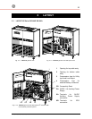
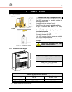
Openings for input and output cable connections
S
G
S
_
2
2
5
-
3
0
0
_
U
P
S
v
i
e
w
t
o
p
_
0
1
U
S
1
,
6
5
0
m
m
6
4
.
9
6
"
1
6
0
m
m
6
.
3
0
"
2
.
7
6
"
4
0
m
m
1
.
5
8
"
7
0
m
m
3
1
.
5
0
"
2
1
.
6
6
"
5
5
0
m
m
8
0
0
m
m
Utility input
Output Load
Battery
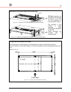
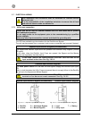
Fig. 3.4.1-2 Opening on top of the cabinet for input and output cables
Utility input
Output Load
6
.
3
0
"
1
6
0
m
m
1
.
7
7
"
5
5
0
m
m
2
1
.
6
6
"
8
0
0
m
m
3
1
.
5
0
"
1
0
0
m
m
3
.
9
4
"
1
,
6
5
0
m
m
6
4
.
9
6
"
S
G
S
_
2
2
5
-
3
0
0
_
U
P
S
v
i
e
w
b
o
t
t
o
m
_
0
2
U
S
4
5
m
m
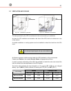
Fig. 3.4.1-3 Opening on the bottom of the cabinet for input and output cables
SG Series openings are
provided on the top and
the bottom of the UPS
for the connection of
input and output cables.
Pay attention to the
position of these
openings, when
choosing the placement
of the UPS.
These openings are
covered with a
protective plate.
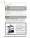
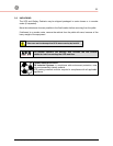
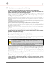
Fixing of the UPS cabinet on the floor
The UPS cabinet is free standing and normally does not require to be bolted to the floor.
The UPS cabinet can be fixed however to the floor by bolting it with the supporting blocks to the
floor.
See Fig. 3.4.1-4.
62.205"
1580mm
35mm
713mm
28.071"
60mm
2.363"
60mm
2.363"
680mm
26.772"
1.378" 1.378"
35mm
==
SGS_225-300_UPS view bottom_02US
Ø 0.47305"
Ø 12mm
Front side
Fig. 3.4.1-4 Fixing of the UPS cabinet on the floor