


g
GE
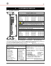
OPM_SGS_ISG_M22_M30_0US_V011.doc 30/38 Installation Guide
SG Series
225 & 300 kVA
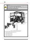
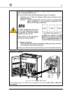
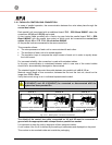
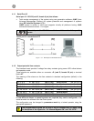
3.10 PARALLEL CONTROL BUS CONNECTION
In cases of parallel operation, the communication between the units takes place through the
control bus cables.
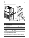
Each parallel unit is equipped with an additional board “P13 – RPA Board IM0006“ where the
connectors J52 (A) and J62 (B) are located.
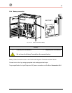
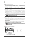
A short control cable provided with a ferrite ring core links the parallel board “P13 – RPA
Board IM0048” with the parallel bus socket on which must be connected the control bus
cables JA and JB on PCB “P34 – Bus Interface IM0048”.
All the parallel units are connected to the same control bus.
This connection allows:
• The microprocessors of each unit to communicate with each other.
• The oscillators of each unit to be locked together.
• The regulation loops to compare the output current of each unit in order to equally share
the Load current.
For increased reliability, this connection is made with redundant cables.
In this way, communication is maintained between units in case one of the control cables
should fail or be accidentally damaged or disconnected.
The standard length of the control bus cable between two parallel unit is 40 ft / 12 m.
Maximal overall length of bus connection, between the first and the last unit, should not be
longer than 276 ft / 84 m.
Verify that control wiring is run in individual separate steel conduit.
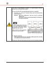
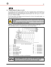
Under no circumstance should the control bus cable connecting JA
(1/2/3/4/5/6/7) and JB (1/2/3/4/5/6/7)
be connected or disconnected after the
system has been powered On.
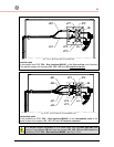
SGT5000_100-150_RPA-IM0048_01
JP3
JP1
JP4
IM 0048
JP2
JP1 JP2
JP4
JP3
JB1
JA1
JB1
JA1
JP2JP1
JP3
JP4
JP3
JP2
JP1
JP4
IM 0048
JB2
JA2
JP1 JP2JB2
JA2
JA3
JB3
JP4
JP3
JP3
JP2
JP1
JP4
IM 0048
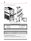
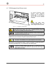
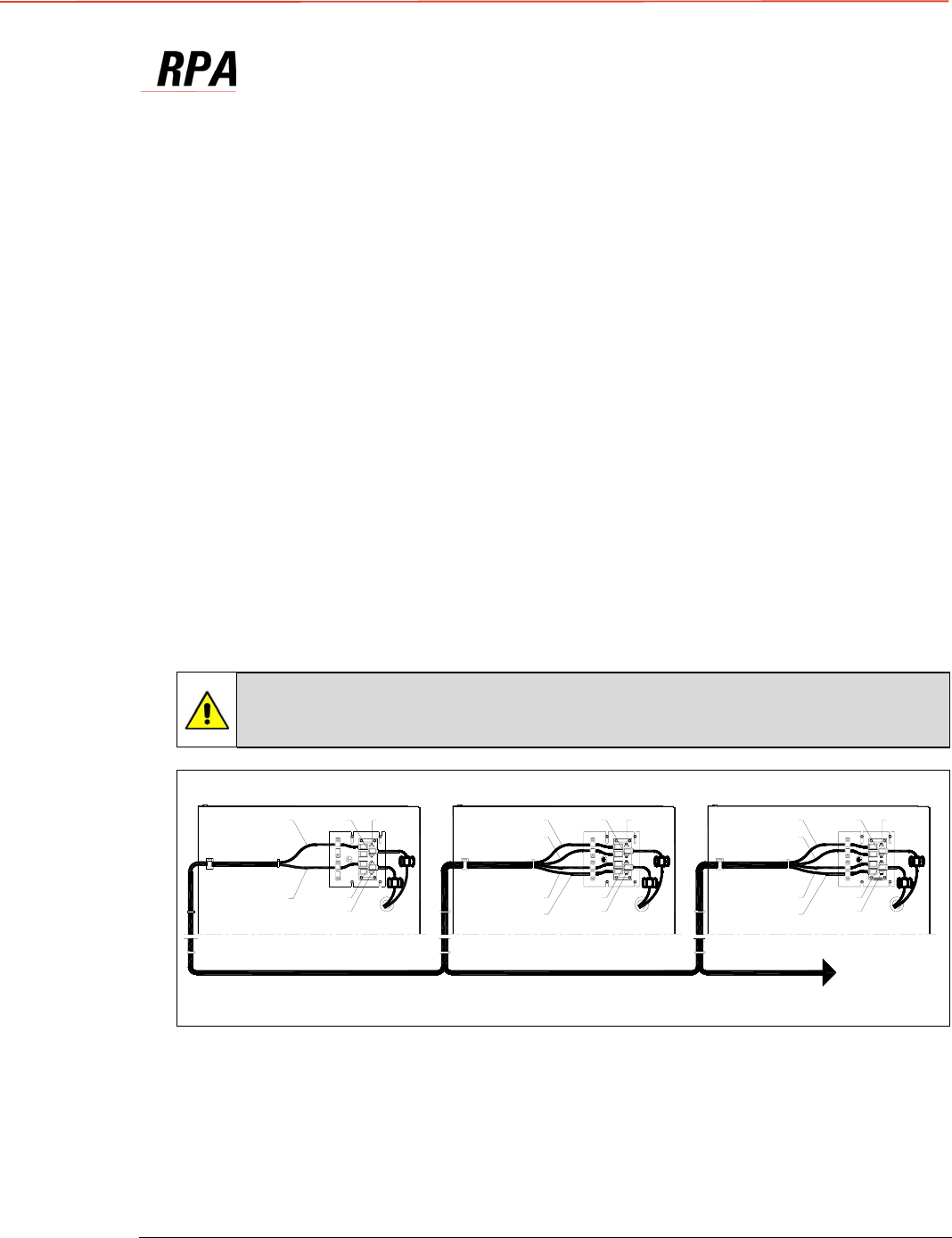
JA1 + JB1 JA2 + JB2 JA3 + JB3
UPS 1 UPS 2 UPS 3
Next parallel
unit 4,5,6,7,8
Fig. 3.10-1 RPA System - Control bus connection
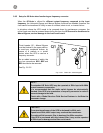
The shield of the control bus cable, connected on JA and JB must be connected to
ground with the appropriate cable clamps fitted on parallel bus socket.
It is important to place the units in sequence of their assigned number.
A unit number from 1 to 8, is defined by the setting of parameters and displayed on the panel.
This number is also marked inside and outside the packaging.