


g
GE
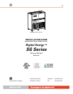
OPM_SGS_ISG_M22_M30_0US_V011.doc 5/38 Installation Guide
SG Series
225 & 300 kVA
Table of contents Page
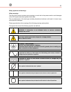
1 IMPORTANT SAFETY INSTRUCTIONS .................................................................6
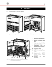
2 LAYOUT ...................................................................................................................9
2.1 LAYOUT
SG SERIES
225 AND 300 KVA ............................................................................9
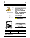
3 INSTALLATION......................................................................................................10
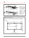
3.1 TRANSPORT ................................................................................................................10
3.1.1
Dimensions and weight .................................................................................................10
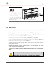
3.2 DELIVERY.....................................................................................................................11
3.3 STORAGE.....................................................................................................................11
3.3.1 Storage of the UPS .......................................................................................................11
3.3.2 Storage of Battery .........................................................................................................11
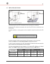
3.4
PLACE OF INSTALLATION ..........................................................................................12
3.4.1 UPS location..................................................................................................................12
3.4.2
Battery location..............................................................................................................14
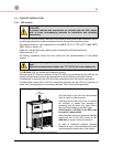
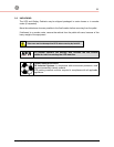
3.5 VENTILATION AND COOLING.....................................................................................15
3.6 UNPACKING .................................................................................................................16
3.7 ELECTRICAL WIRING ..................................................................................................17
3.7.1 Utility input connection ..................................................................................................17
3.7.2 Input/output over current protection and wire sizing......................................................18
3.7.3 Battery over current protection and wire sizing .............................................................19
3.8
WIRING CONNECTION ................................................................................................21
3.8.1 Power connections ........................................................................................................21
3.8.2 Power connection with common input utility..................................................................23
3.8.3 Power connection separate input utility.........................................................................25
3.8.4 Battery connection.........................................................................................................27
3.8.5 Setup for
SG Series
when functioning as frequency converter.........................................28
3.9 POWER WIRING OF PARALLEL UNITS......................................................................29
3.10 PARALLEL CONTROL BUS CONNECTION ................................................................30
3.11
CONTROL BUS CABLE LOCATION ............................................................................32
4 CUSTOMER INTERFACE......................................................................................34
4.1
CUSTOMER INTERFACE ............................................................................................34
4.1.1 Serial Port J3.................................................................................................................35
4.1.2 Output potential free contacts .......................................................................................35
4.1.3 Programmable input free contacts ................................................................................36
4.1.4 Gen Set Signaling (GEN ON)........................................................................................36
4.1.5 AUX external Maintenance Bypass...............................................................................36
4.1.6 Auxiliary Power Supply (APS) 24 VDC / 1A ..................................................................36
4.1.7
EPO (Emergency Power Off) Input contact...................................................................37
5 NOTES....................................................................................................................38
5.1
NOTES FORM ..............................................................................................................38