


g
GE
OPM_SGS_ISG_M22_M30_0US_V011.doc 37/38 Installation Guide
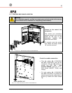
SG Series
225 & 300 kVA
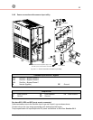
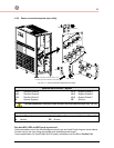
4.1.7 EPO (Emergency Power Off) Input contact
S
G
S
_
2
2
5
-
3
0
0
_
C
u
s
t
o
m
e
r
i
n
t
e
r
f
a
c
e
E
P
O
_
0
1
4
3
2
1
1
2
3
4
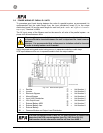
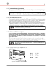
JP3
XB
J2
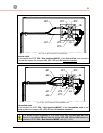
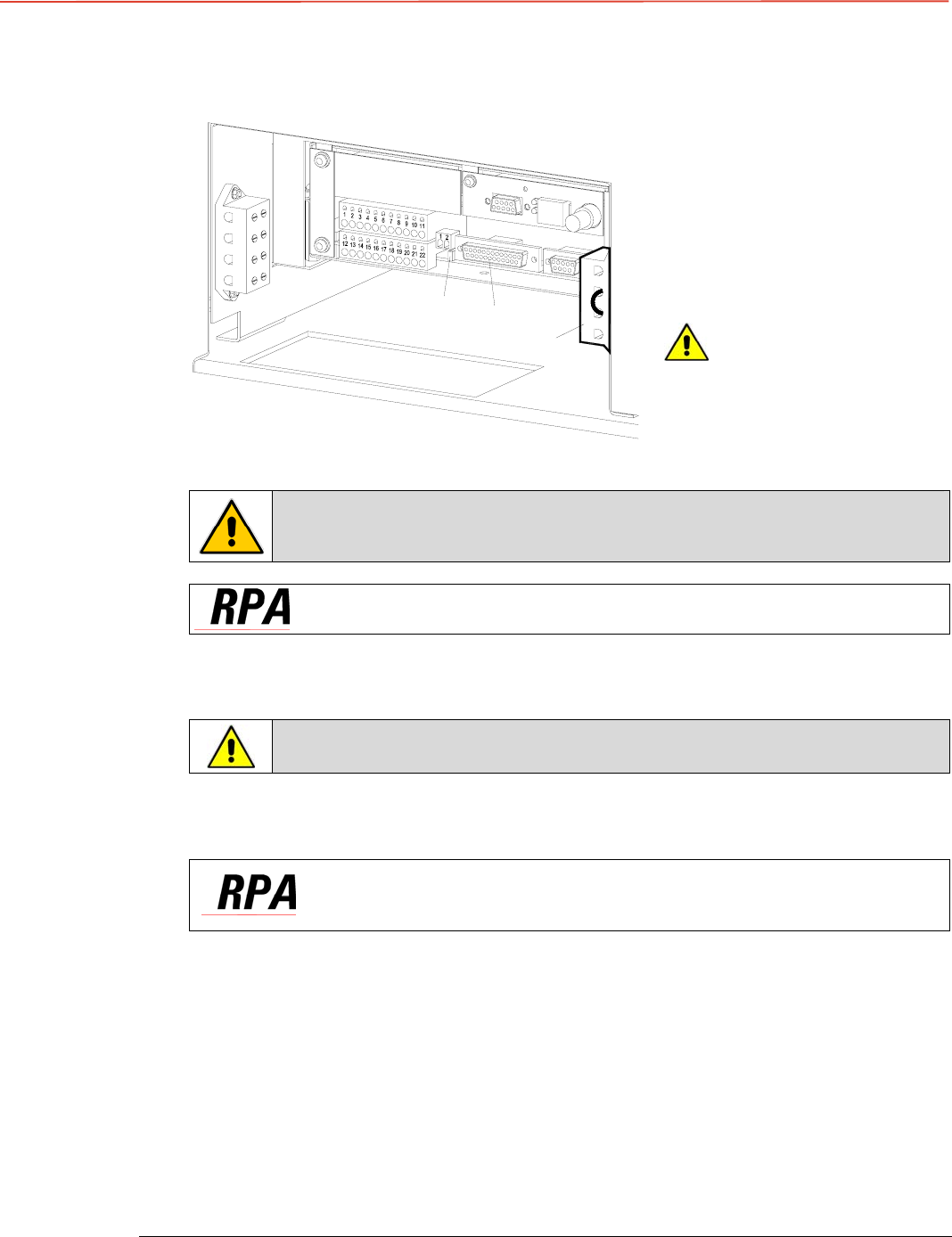
Fig. 4.1.7-1 Terminals for connection EPO
A
n external Emergency switch
(Normally Closed voltage-free
contact) can be connected on
terminals XB / 1 - 4 or connector
J2 / 12 - 25 of the P4 - Interface
Customer.
Remove the cable short-
circuiting terminals XB 2 - 3)
when using this external switch.
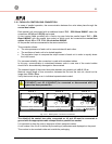
To enable this function, remove cable short-circuiting XB / 2 - 3 on the
Terminal XB and the Jumper JP3 on P4 – Customer Interface, when the
cables have been already connected on XB or J2.
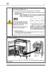
In a parallel system a separate NC (Normally Closed) contact must be
connected individually to each unit.
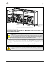
When opened, this contact causes the immediate opening of the Contactors K3, K4, K6, K7
and K8, as well as the shutdown of Rectifier, Inverter and Static-Switch.
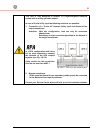
Be aware: The reliability of the system depends on this contact!
After closure of the Emergency contact, a reset is necessary to enable the restart of
the UPS, by pressing the key “O” (inverter off) on the control panel.
In case of a parallel system press the key “O” (inverter off) on the
control panel of each unit connected on parallel bus and having it’s
output switch Q1 closed.