


g
GE
OPM_SGS_ISG_M22_M30_0US_V011.doc 17/38 Installation Guide
SG Series
225 & 300 kVA
3.7 ELECTRICAL WIRING
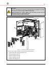
UPS installation and connection must be performed by qualified service
personnel only.
It is the responsibility of the installation technician to ensure that all local
and national electric codes are adhered to.
3.7.1 Utility input connection
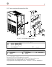
Ensure that the AC and DC external isolators are OFF and locked out to prevent
their inadvertent operation.
Do not apply power to the equipment prior to the commissioning by a qualified
service engineer.
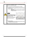
Before any other input connection, connect and check the grounding wire.
The UPS has available input terminations for the Rectifier and Bypass.
The unit may be powered from a common input source or separate input sources if desired.
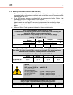
Separate input Rectifier & Bypass (recommended)
The Bypass and Rectifier Inputs are to be powered from different Utility supplies (F1 and
F2 inputs).
In this case, when the Rectifier Input Fuses are opened, the Bypass and the Manual
Bypass are supplied by the other source.
In this case, remove the interconnection links BR1, BR2 and BR3 on the
input terminals or bus bars. See Fig. 3.8.3-2.
Common input Rectifier & Bypass
The
same power source
is to be used for both Bypass Supply and Rectifier Input (input
F3).
Bear in mind that when the Utility Fuses are opened there is a supply failure to the Rectifier
as well as to the Bypass and Manual Bypass.
In this case, the interconnection links BR1, BR2 and BR3 on the input
terminals or bus bars must remain connected. See Fig. 3.8.3-2.
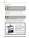
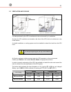
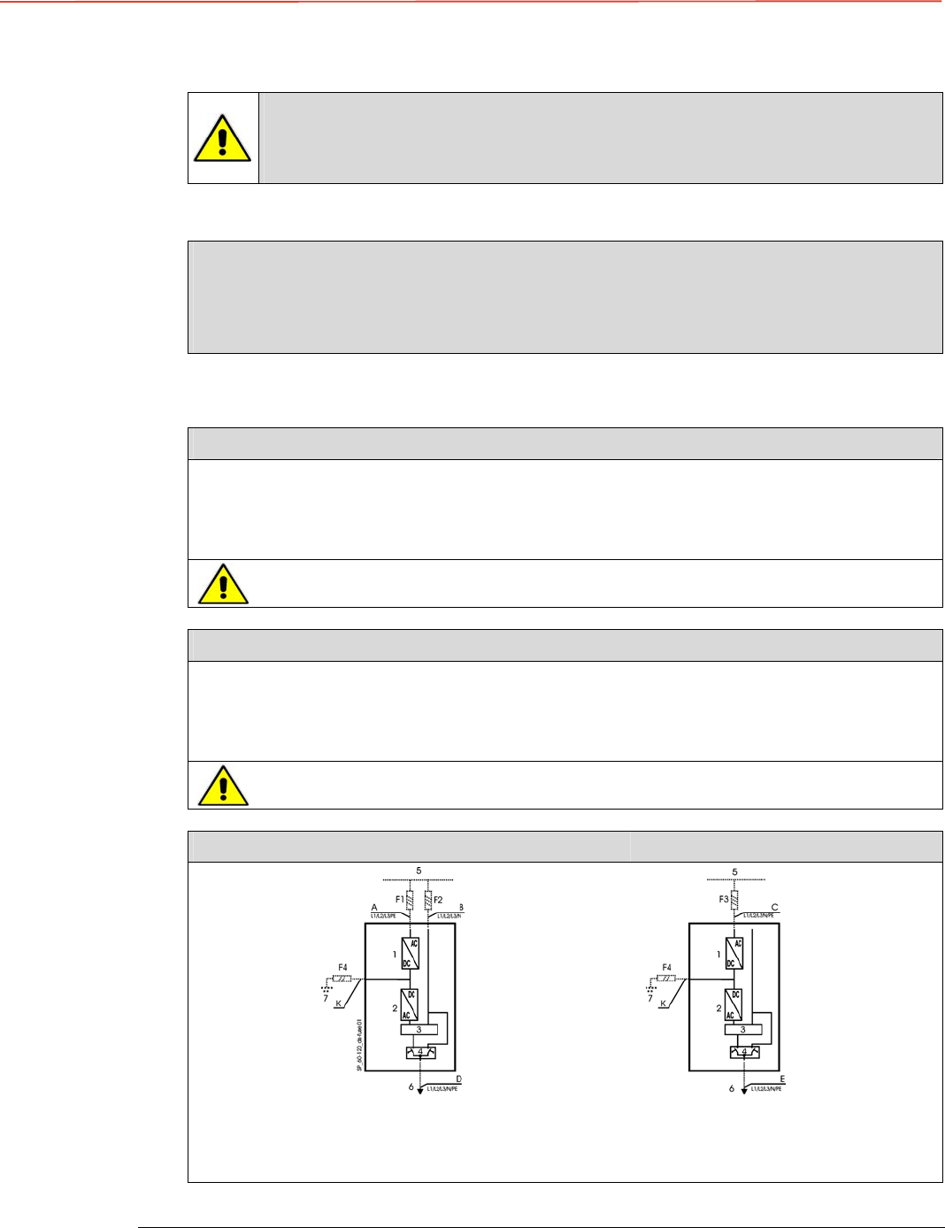
Separate input Rectifier & Bypass (recommended) Common input Rectifier & Bypass
Fig. 3.7.1-1 Separate input Rectifier & Bypass Fig. 3.7.1-2 Common input Rectifier & Bypass
1 = Rectifier
2 = Inverter
3 = Automatic Bypass
4 = Manual Bypass
6 = Load
5 = Utility input
7 = Battery