


g
GE
OPM_SGS_ISG_M22_M30_0US_V011.doc 23/38 Installation Guide
SG Series
225 & 300 kVA
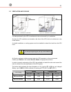
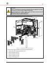
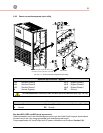
3.8.2 Power connection with common input utility
SGS_225-300_UPS connection common_GE_01US
N
L3
L2
L1
L
O
A
D
PE Load
PE
Input rectifier
1
-
I
N
P
U
T
R
E
C
T
I
F
I
E
R
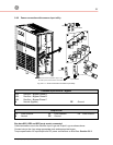
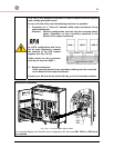
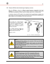
Position of the PE compression lugs in case
the cable input is from the bottom of the UPS
Input rectifier
PE
PE Load
N
L3-1
L2-1
L1-1
Fig. 3.8.2-1 Power connections Common Input Utility
Common Input Rectifier / Bypass
L1-1 Rectifier + Bypass Phase A
L2-1 Rectifier + Bypass Phase B
L3-1
Rectifier + Bypass Phase C
N Neutral (Bypass) PE Ground
Output Load
L1
Load Phase A
L2
Load Phase B
L3
Load Phase C
N Neutral PE Ground
Bus bars BR1, BR2 and BR3 must remain connected.
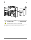
Cable terminations are to the Rectifier Input Lugs and Output Lugs as shown above.
Connect wire to the Lugs using appropriate tools and appropriate torque.
Torque specification for input/output and DC power connections on Bus Bars: Section 3.8.1.