g
GE
OPM_SGS_ISG_M22_M30_0US_V011.doc 18/38 Installation Guide
SG Series
225 & 300 kVA
3.7.2 Input/output over current protection and wire sizing
The cabling of the UPS system has to be sized according to the UPS power rating.
Sizing of circuit breakers, fuses and cables for Input Utility, Output Load and Battery must
meet the requirements of local and national electrical codes.
Before connecting the UPS, verify that the Utility Voltage and Frequency, the Output Load
Voltage and Frequency and Battery Data (cells number, floating voltage, autonomy) are
according to the required specifications.
Output Load configuration may be such that one phase may carry a Load current at 100% of
that phases maximum current rating while the other two phases run at 0% or any combination
in between.
Ensure that the Load does not consist of any equipment that may require high starting currents
such as electric motors, laser printers, etc.
This may cause the UPS to occasionally go into Bypass due to overload conditions
To choose the correct input fuses or circuit breaker, consider the available short-circuit
current
of the system up-stream.
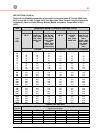
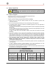
Choose the correct fuse or breaker using current data shown in the chart and the appropriate
NEC code.
The ratings indicated in the following chart do not consider any line voltage drop.
In case of optional input transformer the input protective devices should be sized to allow the
transformer magnetization inrush current.
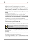
Caution when using four-pole circuit breakers as protection.
A potential problem exists for situations with Non-linear Loads:
The neutral current could be greater than the phase currents.
The three-phase Utility power supply must be symmetrical with respect to ground, due to the
existence of voltage surge protection devices inside the UPS.
If you use
ELCB breaker (Earth Limiting Circuit Breaker)
to protect the input
connections, consider the high leakage current generated by the noise
suppression capacitors.
If these ELCB breakers are strictly necessary, we suggest using the largest type
suitable for non-linear current and for delayed operations.
To ensure coordination when the UPS is configured for separate Bypass and Rectifier Inputs,
special care must be taken in choosing the fuse or circuit breaker ratings installed in the
output distribution circuits.
Protective devices on the output of the UPS should be coordinated with the Bypass Input
circuit protection.
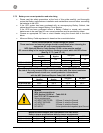
Due to the relatively low short circuit capability of the UPS inverter, a short circuit in the Load
will cause an immediate transfer to Bypass.
The largest fuse or circuit breaker in the output distribution should be rated at no more than
60% of the rating of the protective device supplying the Bypass line.
If circuit selectivity is required while the Load is fed from the inverter (Bypass Utility not
available), the largest fuse or circuit breaker should be rated at no more than 20% of the UPS
output current rating.


