


GFK-2193A 2-1
Installation
This chapter contains information on the following procedures:
Reviewing system power requirements
Installing the PROFIBUS module in the PLC rack
Installing PROFIBUS wiring
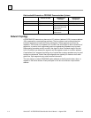
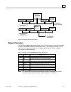
Connecting the Slave to the PROFIBUS network
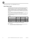
Selecting the proper line type
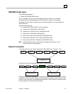
PROFIBUS cable types
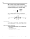
Installing bus termination
Reviewing System Power Requirements
Review the power requirements of your system to ensure that your power supply has
sufficient capacity to support the PROFIBUS Slave module. Power supply load is
automatically calculated by the CIMPLICITY Machine Edition configuration software.
Details on manually calculating power supply load can be found in the Series 90-30
Installation and Hardware Manual, GFK-0356.
Note: High capacity Series 90-30 power supplies IC693PWR330 or IC693PWR331 are
recommended, particularly for systems with CPU350 or higher, or that have
Ethernet adapters and/or multiple PROFIBUS modules. The Series 90-30
PROFIBUS Slave module consumes 450mA at 5VDC (typical).
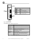
Installing the PROFIBUS Module in the PLC Rack
1. Remove power from Series 90-30 rack.
2. Turn off power to rack.
3. Place the module into slot 1 or higher in the rack (slot 2 or higher in the Main
rack) by hooking the top of the module on the notch above the slot and slowly
lowering the module until it snaps into place.
4. Attach the PROFIBUS cable and terminate as required.
Note: For details about installing Series 90-30 rack systems and modules, refer to the
Series 90-30 Installation Manual and Hardware Manual, GFK-0356.
2
Chapter