


GFK-2121A Chapter 1 Overview and Specifications 1-5
1
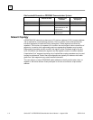
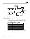
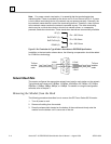
Figure 1-2. Repeaters and bus termination
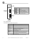
Network Connectors
PROFIBUS connections are created with a 9 pin sub-D connector. A minimum connection
consists of a shielded twisted-pair cable (shield to pin 1 and twisted-pair wires to pins 3
and 8) with terminating connections in the appropriate bus plugs. The pin to signal
conventions are described below.
Pin-out Listing for the PROFIBUS Bus Plug Connector
Pin No. Signal Designation
1 Shield Shield / Protective Ground
2 M24 Ground / Common of the 24V output voltage
3 RxD/TxD-P Receive data / transmission data plus
4 CNTR-P Control signal for repeaters (direction control)
5 DGND Data transmission potential (ground to 5V)
6 VP Supply voltage of the terminating resistance (+ 5V)
7 P24 Output voltage (+ 24V)
8 RxD/TxD-N Receive data / transmission data negative
9 CNTR-N Control signal for repeaters (direction control)
Note: For information on network segment length, network connectors and network
termination, and network baud rate, refer to Chapter 2, “Installation.”
To additional
p
artici
p
ants
Link Segment
(No Participants)
Partici
p
ant Partici
p
ant
Partici
p
antPartici
p
ant
Partici
p
ant
Partici
p
ant
Branch
Segment
Repeater
Connecting
Segments
Remote
Repeate
Remote
Repeater
Termination
Termination