


2-4 Series 90™-30 PROFIBUS Slave Module User's Manual – August 2004 GFK-2193A
2
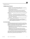
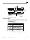
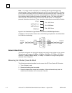
Note: For proper network termination, it is essential that the terminating devices
maintain power. Power is provided by the device on Pin 6 and Ground on Pin 5. If power
is lost to either terminating device, the network may not operate correctly. Generally, the
lone network master device is one of the terminating devices. Therefore, a loss of power
to the network master renders the network inoperable anyway. The other terminating
device may be a critical slave device, which must maintain power, or a separately
powered, stand-alone terminator. These stand-alone devices are commercially available.
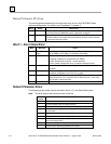
VP (6)
RxD/TxD-P (3)
RxD/TxD-N (8)
DGND (5)
Ru = 390 Ohms
Rt = 220 Ohms
Rd = 390 Ohms
Figure 2-1. Bus Termination for Type A Cable in Accordance to PROFIBUS Specifications
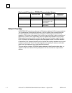
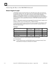
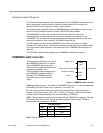
In addition to the termination shown above, the following compensation should be added
for 12 Mbit bus technology:
To/from
another
node
110nH
110nH
To/from
another
node
110nH
110nH
5
4
3
2
1
9
8
7
6
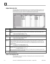
Network Baud Rate
The master configures the appropriate network baud rate for each station on the network.
Typical baud rate values are: 9.6KBps; 19.2KBps; 45.45KBps; 93.75KBps; 187.5KBps;
500KBps; 1.5MBps; 3MBps; 6MBps; or 12MBps. For details on using the configuration
software, refer to chapter 3.
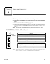
Removing the Module from the Rack
The following procedure describes how to remove the GE Fanuc Series 90-30 master:
1. Turn off power to rack.
2. Remove all cabling from the module.
3. Press the release latch located on the bottom of the module and slowly raise the
module from the bottom until it comes out of the slot.