


3-4 Series 90™-30 PROFIBUS Slave Module User's Manual – August 2004 GFK-2193A
3
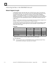
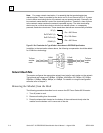
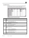
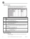
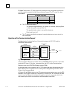
Output Data Area Tab
The output data area describes data sent over the network by the Slave module to the
PROFIBUS Master. These outputs are mapped, using the Output Data Area tab, from
specific memory locations in the PLC where the Slave module resides.
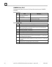
Area
Read-only identifier for the row. Valid range: 1-32.
Type
Data type of area being defined. Valid types are Digital Out, Analog Out, and Empty. The default value is
Empty.
Size
Describes the size of the data area on the network. Set to 0 and read-only if Type is set to Empty. Valid
ranges:
If Type is set to Digital Out (Byte): 0—244
If Type is set to Analog Out (Word): 0—122
Note: The total number of output bytes for all entries cannot exceed 244.
Units
This read-only field gives the units for the Type specified.
If Type is set to Empty or Digital Out: Byte
If Type is set to Analog Out: Word
Ref
Address
Location in PLC memory where the data to be sent is mapped. This field is read-only if Size is set to 0.
This is a produced range and can be any range in %AI, %I, %Q, %G, %AQ, %R, %T, or %M. If Type is
Digital Out and the number of bytes (Size) is odd, an address in discrete memory must be used: %I, %Q,
%G, %M, or %T. Overlaps with another produced range are not considered fatal and can be included in a
valid configuration.
Default: For Digital Out, next available address in %Q
For Analog Out, next available address in %AQ
Length
The length of the reference mapped to the area.
Allowable ranges: For discrete memories: 0, 8, 16 ... X
For register memories: 0, 1, 2 ... X
where X is the required length to hold the entire data area. The default value is the space required to map
bytes specified by the entries in Type and Size.
Note: If an output data area is defined (Type and Size are specified) but Length is set to 0, a value of 0 is sent to the
Master for that data area.
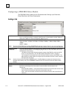
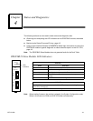
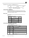
Power Consumption Tab
The information in this tab is read-only. It displays the power consumed by the module
from the PLC backplane.