


4-4 Series 90™-30 PROFIBUS Slave Module User's Manual – August 2004 GFK-2193A
4
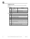
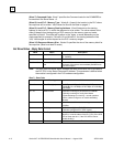
FT Output: The function’s FT (fault) output can provide an output to optional logic that can
verify successful completion of the Communications Request. The FT output can have
these states:
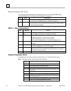
FT Output Truth Table
Enable Input Status Does an Error Exist? FT output
Active No Low
Active Yes High
Not active No execution Low
The FT output is set High if:
The specified target address is not present (for example, specifying Rack
1 when the system only uses Rack 0).
The specified task number is not valid for the device.
Data length is set to 0.
The FT output can either be connected to another device, such as a set coil, or
can be left open.
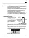
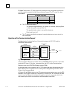
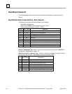
Operation of the Communications Request
The figure below illustrates the flow of information between the PLC CPU and the
PROFIBUS Slave module:
Status bits
Requested data
Command
PLC CPU
Ladder
program
•
COMMREQ
CPU
memory
•
Data
•
Status word
PROFIBUS Slave
Module
Firmware
instructions
On-board
memor
y
PLC
Back
p
lane
PROFIBUS
networ
k
to Master
Figure 4-2. Operation of the PROFIBUS Communications Request
A Communications Request is initiated when a COMMREQ ladder instruction is activated
during the PLC scan. At this time, a command from the PLC via the Communications
Request is sent to the PROFIBUS Master module (PBM).
At the conclusion of every request, the PLC CPU reports the status of the request to the
Status Word, which is a location in PLC memory that is designated by the Status Word
Pointer in the Command Block.
In Figure 4-2, the PBM is shown in the CPU rack and communications occur over the PLC
backplane. If the PBM is located in an expansion or remote rack, the commands and data
are sent over the CPU rack’s backplane, through the expansion or remote cable to the
rack containing the PBM, and across that rack’s backplane to the PBM.