HARDWARE
20 CIO Remote CAN Digital I/O Module GEK-106465A
3.4.2. BOARD OPTION 2
Option 2 I/O board includes two groups of 4 inputs with one common, in terminals 9 to 10. It also includes 6 auxiliary
outputs, in terminals 19 to 30 with normally open contacts and two current sensing (latching) outputs.
Besides, there are 2 groups of inputs for trip circuit supervision. The first group includes two isolated digital inputs,
terminals 1-2 and 3-4. The second group, symmetrical and identical to the first, is formed by isolated voltage inputs
15-16 and 17-18.
Inputs in both groups are wet contacts, this means they need to receive a positive in the terminal labeled as + coming
from a power supply whose negative is connected to the terminal labelled as -.
Using voltage detectors and current sensing, it is possible to implement several trip or close circuit supervision
schemes, as well as protection of the unit output contact.
In order to implement these schemes, it is not necessary to perform any setting in the unit. Internal functions are
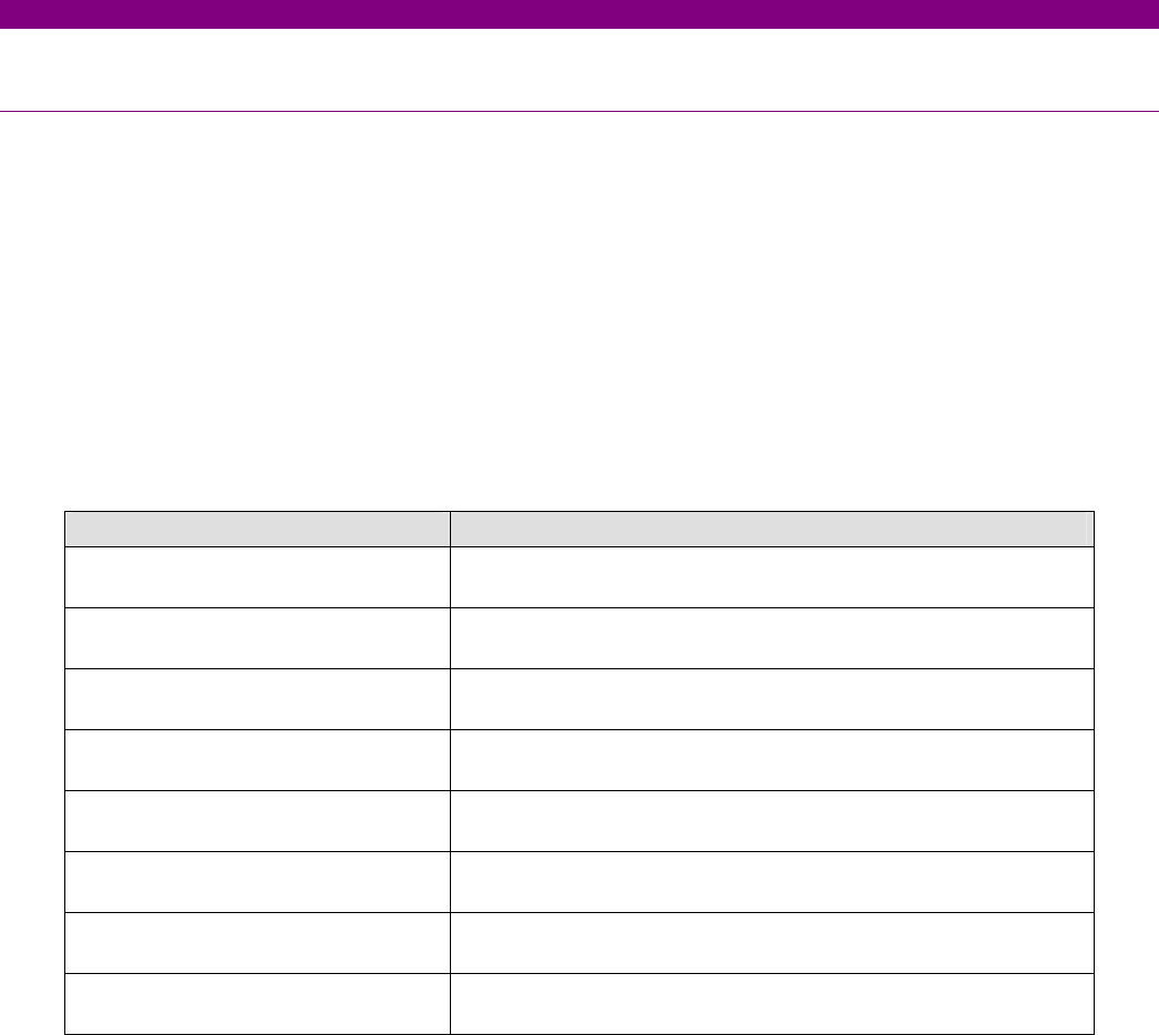
always operative and provide the following logic operands:
OPERAND DESCRIPTION
CONTACT INPUT_00_08
(Va_COIL1)
Active when voltage is detected in terminals 1 - 2 (circuit 1)
CONTACT INPUT_00_09
(Vb_COIL1)
Active when voltage is detected in terminals 3 - 4 (circuit 1)
CONTACT INPUT_00_10
(Va_COIL2)
Active when voltage is detected in terminals 15 - 16 (circuit 2)
CONTACT INPUT_00_11
(Vb_COIL1)
Active when voltage is detected in terminals 17 - 18 (circuit 2)
CONTACT INPUT_00_12
(O7_SEAL)
Active if current is detected by sensor in output O7 (F31-F33)
CONTACT INPUT_00_13
(O8_SEAL)
Active if current is detected by sensor in output O8 (F34-F36)
CONTACT INPUT_00_14
(SUP_COIL1)
Active when continuity is detected in circuit 1
CONTACT INPUT_00_15
(SUP_COIL2)
Active when continuity is detected in circuit 2
A continuity failure is detected in a circuit when both voltage detectors (Va and Vb) detect lack of voltage during more
than 500 ms. This function is not influenced by the breaker status.
These operands can be associated to internal signals (virtual outputs), LEDs or unit outputs, to issue alarm signals or
to block elements, for example for blocking the Breaker close if an abnormality is detected in the trip circuit.
Available schemes are as follows:
1. Without supervision
2. With current supervision (with seal-in)
3. With simple voltage supervision
4. With double voltage supervision
5. With current and simple voltage supervision (with seal-in)
6. With current and double voltage supervision (with seal-in)


