


HARDWARE
GEK-106465A CIO Remote CAN Digital I/O Module 25
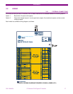
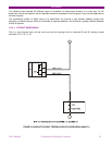
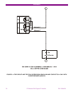
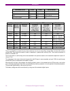
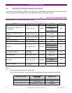
For the second case shown on the table, open breaker, its auxiliary contact 52/a remains open, and current cannot
flow through it for detecting continuity. In order to correctly monitor the circuit, a resistor must be used, not included in
the protection, connected in parallel. The value of resistance will be selected so that the V 52/a input circuit minimum
detection current flows, but not as high as to activate the breaker tripping coil. The figure shows the following
equation:
V min – 15
R = -------------------
2
Where:
Vmin Is the minimum voltage, in Volts, expected in the battery (e.g. 80% of Vn)
R Resistance, in kilo ohms.
2 2 mA of approximate current flowing through input V 52/a
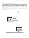
As shown in the second case in the table, with an open breaker, as current will flow through R if there is continuity in
the WHOLE tripping circuit, voltage will be detected in input V 52/a.
This works correctly in steady state. However, if the breaker trips, while it is opening, the V 52/a input signal can be
deactivated without this meaning that the circuit is not correct. This is due to the fact that the tripping relay, terminals
35-36, short circuits input V 52/a temporarily.
Therefore, if there is a trip signal, it is admitted that no signal will be detected during a period of 1 s to allow the
breaker to open, and reopen the tripping relay 35-36.
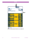
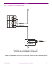
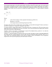
FIGURE 3-11 shows the possibility of monitoring the circuit only when the breaker is closed. In this case resistance R
will not be used, but it must be observed in the unit logic, that the corresponding signal CONTACT INPUT_00_15
(SUP_COIL2), will be activated showing a failure when the breaker is open, and therefore it will be required to
supervise the continuity failure signalling by the breaker status information.