


ACCEPTANCE TESTS
GEK-106465A CIO Remote CAN Digital I/O Module 41
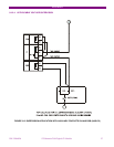
6.6. COMMUNICATION WITH THE MASTER UNIT
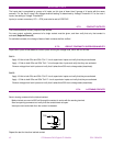
1. Connect the master unit to the CIO. Verify that the BUS LED blinks indicating communication between both
units.
2. Verify, using the master unit Setup program, that the CIO boards setting options are available. For example,
using an F650 as master unit, verify in EnerVista F650 Setup, that the "Actual > Inputs/Outputs > I/O
Board Status > Board H Status" and "Actual > Inputs/Outputs > I/O Board Status>Board J Status"
appear as active.
6.7. INPUTS AND OUTPUTS
During all tests, the screw on the rear of the relay must be grounded.
6.7.1. DIGITAL INPUTS
During this test, the user will determine the activation/deactivation points for every input in the relay for the set voltage
value of 30 Volts.
Verify that the error does not exceed +/- 10% (+10% on activation, -10% on deactivation)
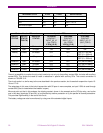
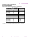
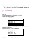
Default board settings for the input test are as follows:
Settings/Control Elements/Inputs Outputs/Board X
I/O Board Type 1
Voltage Threshold A_01 30 V
Voltage Threshold B_01 40 V
Debounce Time A_01 15 ms
Debounce Time B_01 15 ms
Input Type 01 00 (CC1) POSITIVE
... ...
Input Type 01 15 (CC16) POSITIVE
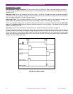
The inputs test is completed by groups of 8 inputs, as this type of board has 2 groups of 8 inputs with the same
common. For the first 8 inputs, the voltage threshold setting is determined by Voltage Threshold A. For the next 8
inputs, the setting is Voltage Threshold B.
Inputs (or contact converters, CC1 – CC15) must also be set to POSITIVE.
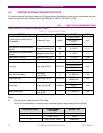
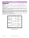
I/O Board Type 2
Voltage Threshold A_01 30 V
Voltage Threshold B_01 40 V
Debounce Time A_01 5 ms
Debounce Time B_01 5 ms
Input Type 01 00 (CC1) POSITIVE
... ...
Input Type 01 07 (CC8) POSITIVE