


ACCEPTANCE TESTS
40 CIO Remote CAN Digital I/O Module GEK-106465A
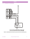
6.3. ISOLATION TESTS
During all tests, the screw located on the rear of the relay must be grounded.
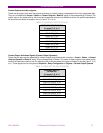
For verifying isolation, independent groups will be created, and voltage will be applied as follows:
2000 RMS volts will be applied progressively
among all terminals in a group, short-circuited between them
and the case, during one second.
2000 RMS volts will be applied progressively
between groups, during one second.
WARNING:
No communication circuit shall be tested for isolation.
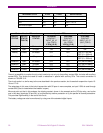
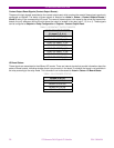
Groups to be created will depend on the type of modules included in the CIO, selectable according to the model.
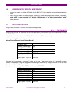
The following table shows the different groups depending on the module type:
SOURCE 1: I/O OPTION 1 I/O OPTION 2.
G1: K10, K18 G1: (Inp. 1)1…9 G1 (Spv 1): 1...4
G2: K13, K14, K15 G2: (Inp. 2) 10…18 G2 (Inp. 1): 5...9
G3: (Out.) 19…36 G3 (Inp. 2): 10…14
G4 (Spv 2): 15...18
G5 (Out.): 19...30
G6 (Out.): 31…36
6.4. INDICATORS
Feed the unit and verify that the Ready LED lights up.
Communicate with the master unit and verify that the communication LED lights up showing activity on the CAN bus.
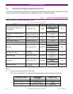
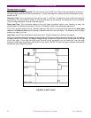
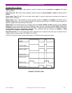
6.5. POWER SUPLY TESTING
Feed the unit to the minimum and maximum voltage. For each voltage value, verify that the alarm relay is activated
when there is voltage, and it is deactivated when there is no feed. If the power supply source incorporates AC feed,
this test will be performed also for VAC.
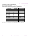
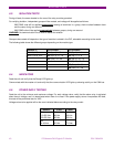
Voltage values to be applied will be the ones indicated below according to the relay model:
SUPPLY V min. V max.
HI
110-250 Vdc
120-230 Vac
88 Vdc
96 Vac
300 Vdc
250 Vac
LO
24-48 Vdc
20 Vdc
57.6 Vdc