


I/O MODULES DESCRIPTION
GEK-106465A CIO Remote CAN Digital I/O Module 37
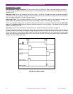
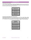
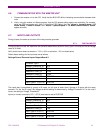
Contact Outputs activation signals:
These are the signals that mark the physical activation of contact outputs, independently from their associated logic.
They can be obtained at Actual > Status > Contact Outputs > Board X, being X the corresponding I/O board. The
output name is the same both for the mixed and supervision boards; the difference will be the symbol associated to
the slot where the board is located in the unit (slot F, G, H or J).
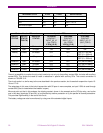
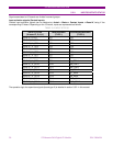
TABLE 5-3 CONTACT OUTPUT STATUS
CONTACT OUTPUT STATUS
(X: board F, G, H, J)
CONT OP_X_01
CONT OP_X_02
CONT OP_X_03
CONT OP_X_04
CONT OP_X_05
CONT OP_X_06
CONT OP_X_07
CONT OP_X_08
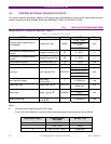
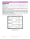
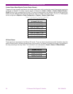
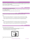
Contact Output Activation Signals (Contact Output Operates):
These are the logic signals associated to contact outputs that produce their activation. Actual > Status > Contact
Outputs Operates > Board X, being X the corresponding I/O board. The name of these outputs is the same for the
mixed and supervision boards, the only difference will be the slot where the output is located in the relay (slot F, G, H
or J). These signals can be configured at Setpoint > Relay Configuration > Outputs > Contact Output Operate.
TABLE 5-4 CONTACT OUTPUT OPERATES
CONTACT OUTPUT
OPERATES
(X: board F, G, H, J)
CONT OP OPER_X_01
CONT OP OPER_X_02
CONT OP OPER_X_03
CONT OP OPER_X_04
CONT OP OPER_X_05
CONT OP OPER_X_06
CONT OP OPER_X_07
CONT OP OPER_X_08