


ACCEPTANCE TESTS
42 CIO Remote CAN Digital I/O Module GEK-106465A
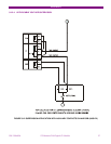
The inputs test is completed by groups of 4 inputs, as this type of board has 2 groups of 4 inputs with the same
common. For the first 4 inputs, the voltage threshold setting is determined by Voltage Threshold A. For the next 4
inputs, the setting is Voltage Threshold B.
Inputs (or contact converters, CC1 – CC8) must also be set to POSITIVE.
6.7.2. CONTACT OUTPUTS
The correct activation of every output will be verified.
For every output, activation command of a single contact must be given, and then verify that only that contact is
activated (Setpoint/Force IO)
For switched contacts, the change of state of both contacts shall be verified.
6.7.3. CIRCUIT CONTINUITY SUPERVISION INPUTS
Supervision inputs will be tested as normal inputs, revising the voltage level, which will be 19 Volts.
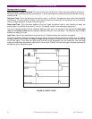
Coil 1:
Apply 19 Vdc to both 52/a and 52/b ”Coil 1” circuit supervision inputs and verify that they are activated.
Apply -19 Vdc to both 52/a and 52/b ”Coil 1” circuit supervision inputs and verify that they are activated.
Remove voltage from both inputs and verify that it takes them 500 ms to change state (deactivate).
Coil 2:
Apply 19 Vdc to both 52/a and 52/b ”Coil 2” circuit supervision inputs and verify that they are activated.
Apply -19 Vdc to both 52/a and 52/b ”Coil 2” circuit supervision inputs and verify that they are activated.
Remove voltage from both inputs and verify that it takes them 500 ms to change state (deactivate).
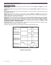
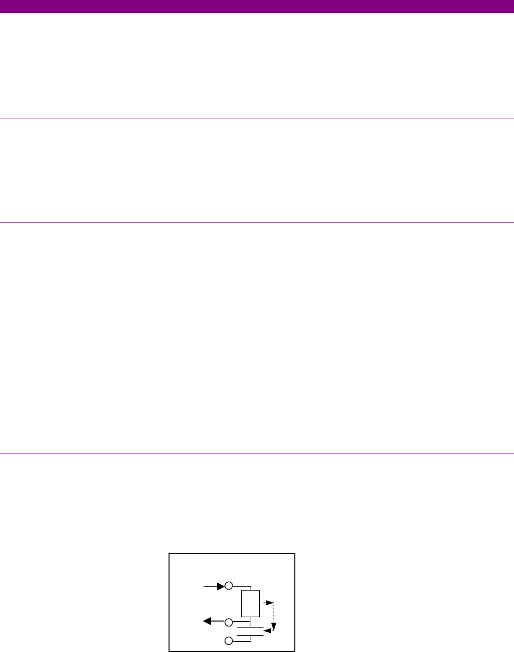
6.7.4. LATCHING CIRCUITS
Send a closing command to the latched contact.
Make circulate a current of 200 mA through the contact in series with the sensing terminal.
Send an opening command and verify that the contact does not open.
Interrupt current and check than the contact is released.
Repeat the test for the other latched contact
200
I