


I/O MODULES DESCRIPTION
32 CIO Remote CAN Digital I/O Module GEK-106465A
5.2. CONTROL SETTINGS FOR INPUTS/OUTPUTS
This section explains the settings related to CIO inputs/outputs. Modification of these values is performed using the
master unit communication software, EnerVista F650Setup for F650, or GE-CONF for F600.
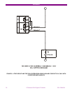
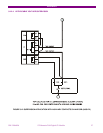
5.2.1. INPUT/OUTPUT BOARDS SETTINGS
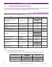
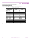
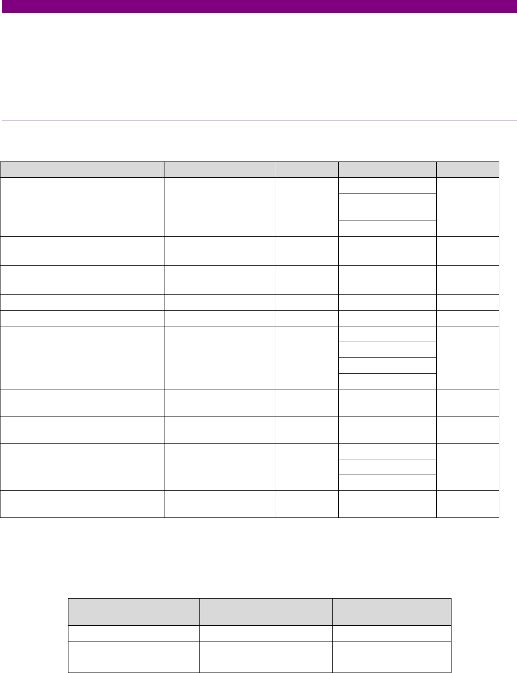
Settings relative to I/O boards are described in table 5-1:
TABLE 5-1 I/O BOARD SETTINGS
SETTING HMI DEFAULT RANGE STEP
16 INP + 8OUT
8 INP + 8OUT +
SUPV
I/O board type (available only for
CIO modules)
I/O Board_X Type NONE
NONE
N/A
Input activation voltage threshold
Group A
Voltage Threshold A_X 80 0 – 255 V 1 V
Input activation voltage threshold
Group B
Voltage Threshold B_X 80 0 – 255 V 1 V
Debounce time Group A Debounce Time A_X 15 1 – 50 ms 1 ms
Debounce time Group B Debounce Time B_X 15 1 – 50 ms 1 ms
POSITIVE-EDGE
NEGATIVE-EDGE
POSITIVE
Input type Input Type_X_CCY POSITIVE
NEGATIVE
N/A
Input signal time delay
Delay Input
Time_X_CCY
0 0 – 60000 ms 1 ms
Output logic type Output Logic_X_0Z POSITIVE
POSITIVE-
NEGATIVE
N/A
NORMAL
PULSE
Output type Output Type_X_0Z NORMAL
LATCH
N/A
Output pulse length
Pulse Output
Time_X_0Z
0 0 – 60000 ms 1 ms
Being:
X I/O board name, depending on the CIO model.
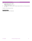
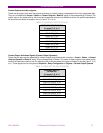
For the I/O board selection in the relay model, associated digits to each board type are as follows:
ASSOCIATED DIGIT
F650PC BOARD
SETTINGS
BOARD TYPE
0 NONE None
1 16 INP+ 8OUT Mixed
2 8 INP +8 OUT +SUPV Supervision