


GE MDS Intrepid-HC HP Installation Guide
1-16
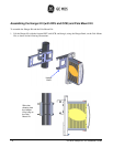
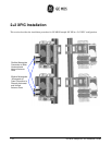
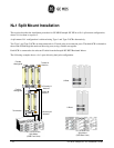
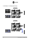
N+1 Split Mount Installation
This section describes the installation procedure for GE MDS Intrepid-HC HP in an N+1 split mount configuration,
where N is less than or equal to 5.
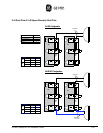
A split mount N+1 configuration is achieved using Type-1 and Type-2 OCBs alternatively.
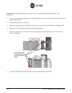
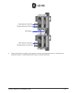
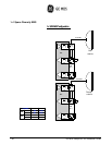
Two Type 1 and Type 2 OCBs are interconnected via U bends at the rear extension ports. The third OCB is chained to
the second OCB through the main and diversity ports, using a flexible waveguide.
Each OCB is connected to the relevant IF cable from the Intrepid-HC HP/T Baseband Indoor.
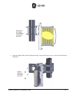
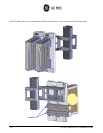
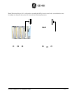
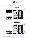
The following example shows a 4+1 space diversity dual pole configuration.
To Diversity V
Antenna
To Main V
Antenna
To Main H
Antenna
Termination
Flexible
Waveguide
Flexible
Wave
g
uide
U Bend
4+1 SD Dual Pole
Split Mount
(OCB Front View)
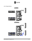
4+1 SD Dual Pole
Split Mount
(
OCB
Rear
View
)
To Diversity H
Antenna
U Bend