


3-6 Section 3: Installation
February 3, 2000 70055MP Revision D
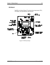
Alarm Configuration Jumpers
Jumpers JP18 and JP19 set the annunciator relay outputs to normal or
inverted. Jumper JP13 configures the Acknowledge Alarm button. Refer to
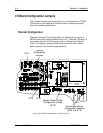
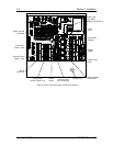
Table 3-3 for jumper positions. Refer to Figure 3-3 for jumper locations.
NOTE: JP13 must always be installed.
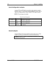
Table 3-3: Alarm Configuration
Jumper Position Description
JP18 INV
NORM
Annunciator 1 Output Inverted.
Annunciator 1 Output Normal.
JP19 INV
NORM
Annunciator 2 Output Inverted.
Annunciator 2 Output Normal.
JP13 Installed
Removed
Configures the Alarm Acknowledge button for use.
Not applicable.
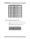
Ground Jumpers
Jumpers JP10 and JP14, when installed, are set to earth ground. These
jumpers must always be installed for accurate and safe operation.
WARNING: Jumpers JP10 and JP14 must always be installed for accurate
and safe monitor operation.