


Section 3: Installation 3-7
70055MP Revision D February 3, 2000
Wiring
Overview
Prior to starting any wiring procedures:
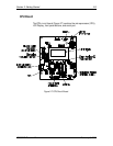
Pull the power fuse (F1) on the Power Supply board.
• Securely ground the LTC-MAP 2130 at the ground lug.
CAUTION: Pull the power board fuses or remove F1 on the I/O board before
making connections.
WARNING: The LTC-MAP 2130 Monitor must be properly grounded before
placing the unit in service. An improper or missing ground can create a
safety hazard.
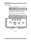
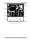
Refer to Figure 3-4 for fuse and ground lug locations.
LTC-MAP 2130 wiring consists of:
• Wiring the sensors.
• Wiring a tap position indicator (if used).
• Wiring the AC current inputs.
• Wiring the AC voltage inputs.
• Wiring the digital inputs.
• Wiring the annunciator outputs.
• Wiring the internal heater.
• Wiring power.
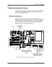
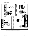
Refer to Figure 3-4 for I/O Board Terminal Locations. Refer to Figure 3-5 for
an example of a typical wiring diagram.