


Section 3: Installation 3-17
70055MP Revision D February 3, 2000
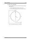
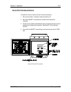
Wiring the AC Voltage Inputs
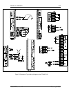
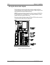
Connect voltage signals to the designated terminals (Voltage Input #1, #2,
#3, #4) on the wiring and installation diagrams. Refer to Figure 3-5 for
terminal location.
NOTE: The signal specification range for Voltage Inputs #1, #2, #3, and #4
are 0 to 300 Vrms. If your signal input is different, contact Support Services
as noted on back cover.
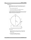
Wiring the AC Current Inputs
There are two types of current inputs - powered CT and unpowered CT
(e.g., Clamp On AC Current Transducer).
Connections for unpowered CT’s are not polarity sensitive. Connect the CT
between the A, B, or C Current terminals (refer to Figures 3-4 and 3-5).
Connections for powered (active) CT’s are polarity sensitive. Refer to
information on the active CT’s connection points for proper polarity.
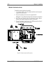
Wiring the Digital Inputs
The LTC-MAP 2130 monitor collects output data from the Control Isolator at
the digital inputs. (See Figure 3-4 for Control Isolator Input terminal
locations.)
NOTE: Refer to Document No. 70062MP for specific information on
the Control Isolator, Part No. 40041MP.
1. Mount the Control Isolator(s) per the guidelines provided in the
documentation provided with the Control Isolator.
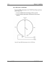
NOTE: The control Isolators are provided with a 10 foot cable;
therefore, when selecting a mounting location, be sure it is within 10
feet of the monitor.
2. Connect the output cable of the Control Isolator to the First Control
Isolator Input (digital channels 1-8) as designated on the wiring and
installation diagrams.
3. If there is a second Control isolator installed, connect the output cable
of the Control Isolator to the Second Control Isolator Input (digital
channels 9-16) as designated on the wiring and installation diagrams.
NOTE: If only one Control Isolator is installed, it must be connected to the
First Control Isolator input terminals on the I/O board.