


2–2 P485 MODBUS TO PROFIBUS CONVERTER – USER GUIDE
INSTALLATION
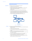
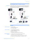
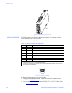
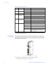
Figure 2-1: P485 electrical connections
PROFIBUS CONNECTOR The Profibus connector is indicated as A in the figure above. This connector is used to
connect the P485 to the Profibus network.
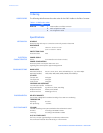
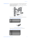
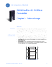
The pin assignments for the Profibus connector are shown below.
Figure 2-2: Profibus connector
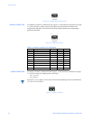
The following Profibus connectors are recommended:
• Profibus Max standard, part number 134928 and Profibus reversed, part number
104577, from http://www.erni.com
• Fast connect bus connector, part number 6GK1500-0FC00 or 6ES7 972-0BA50-0XA0,
from http://www.siemens.com
E
A
B
C
D
Table 2–1: Profibus connector pin assignments
Pin Signal Description
1- -
2- -
3 B-Line Positive RxD/TxD (RS485)
4 RTS * Request To Send
5 GNDBUS ** Isolated ground from the RS485 side
6 +5 V BUS ** Isolated +5V output from the RS485 side (80 mA maximum)
7- -
8 A-Line Negative RxD/TxD (RS485)
9- -
* Used in some equipment to determine the direction of transmission. However, in normal
applications only A-Line, B-Line and Shield are used.
** Used for bus termination. Some devices such as optical transceivers (RS485 to fibre optics) may
require power from these pins.
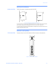
51
69
(female)