


INSTALLATION
P485 MODBUS TO PROFIBUS CONVERTER – USER GUIDE 2–3
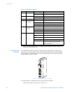
CONFIGURATION CABLE The PC connector is indicated as B in Figure 2-1: P485 electrical connections on page 2–2.
This connector is used to connect the P485 to a PC using the configuration cable for
configuration and monitoring purposes.
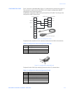
A P485/D485 configuration cable can be purchased from GE Multilin. The wiring for the
configuration cable is shown below.
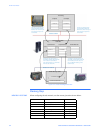
Figure 2-3: Configuration cable
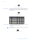
The pinout for the modular 4/4 RJ11 connector (connects to the P485) is shown below.
Figure 2-4: Configuration cable (P485 end)
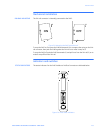
The pinout for the DSUB 9-pin serial plug (connects to the PC) is shown below.
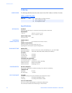
Table 2–2: Configuration cable pin assignments (P485 end)
Pin Description
1 Signal ground
2 Signal ground
3 RS232 Rx, data input to P485
4 RS232 Tx, data output from P485
Table 2–3: Configuration cable pin assignments (PC end)
Pin Description
1 Not connected
2 RS232 Rx, data input to PC
3 RS232 Tx, data output from PC
4 Not connected
5 Ground
6 to 9 Not connected
1
2
3
4
5
6
7
8
9
1
2
3
4
D-sub 9 female (PC) Modular 4/4 RJ11connector (P485)
Ground
Ground
Rx
Tx
RS232 Tx
RS232 Rx
Ground
Connects to PC serial port
Connects to P485
1
2
3
4